Function | Selections or |
Prompt | Range of Setting |
Lower Display | Upper Display |
100PCT
RLYSTATE
1OF 2OF
1ON 2OF
1OF 2ON 1ON 2ON
RLY TYPE
MECHAN
SOL ST
Parameter Definition
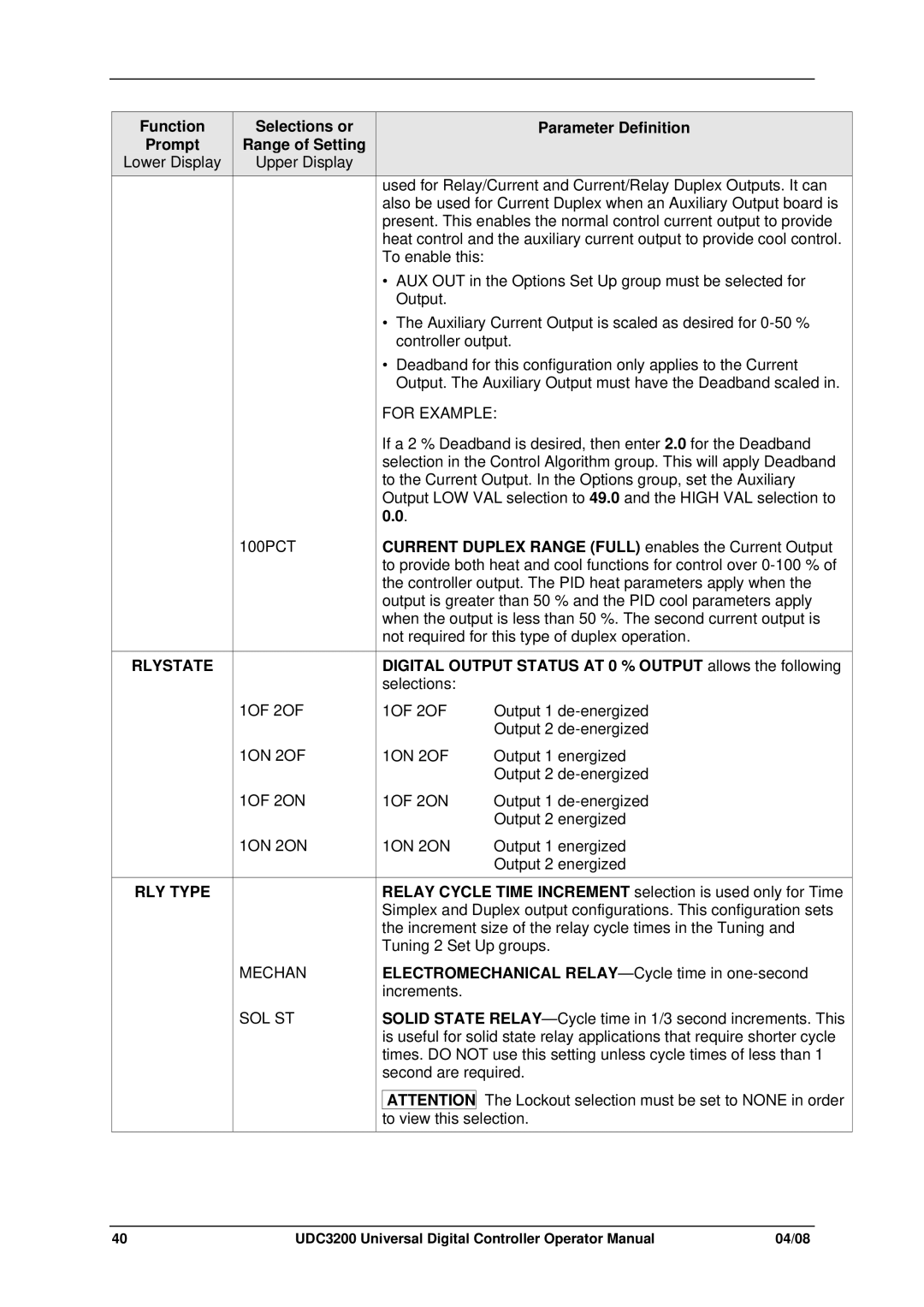
used for Relay/Current and Current/Relay Duplex Outputs. It can also be used for Current Duplex when an Auxiliary Output board is present. This enables the normal control current output to provide heat control and the auxiliary current output to provide cool control. To enable this:
•AUX OUT in the Options Set Up group must be selected for Output.
•The Auxiliary Current Output is scaled as desired for
•Deadband for this configuration only applies to the Current Output. The Auxiliary Output must have the Deadband scaled in.
FOR EXAMPLE:
If a 2 % Deadband is desired, then enter 2.0 for the Deadband selection in the Control Algorithm group. This will apply Deadband to the Current Output. In the Options group, set the Auxiliary Output LOW VAL selection to 49.0 and the HIGH VAL selection to 0.0.
CURRENT DUPLEX RANGE (FULL) enables the Current Output to provide both heat and cool functions for control over
DIGITAL OUTPUT STATUS AT 0 % OUTPUT allows the following selections:
1OF 2OF
1ON 2OF
1OF 2ON
1ON 2ON
RELAY CYCLE TIME INCREMENT selection is used only for Time Simplex and Duplex output configurations. This configuration sets the increment size of the relay cycle times in the Tuning and Tuning 2 Set Up groups.
ELECTROMECHANICAL
SOLID STATE
ATTENTION The Lockout selection must be set to NONE in order to view this selection.
40 | UDC3200 Universal Digital Controller Operator Manual | 04/08 |