DC Controller
1Remove the Printer Covers.
2Disconnect the motor connector from the motor (Figure
3Disconnect the Solenoid connector from the DC Controller (Figure
4Remove the back sheet metal plate and disconnect the PS202/PS204 connector (Figure
5Remove the AC Cable cover and disconnect the AC Cable from the DC Controller (Figures
6Tip the printer on its top, with the front facing you.
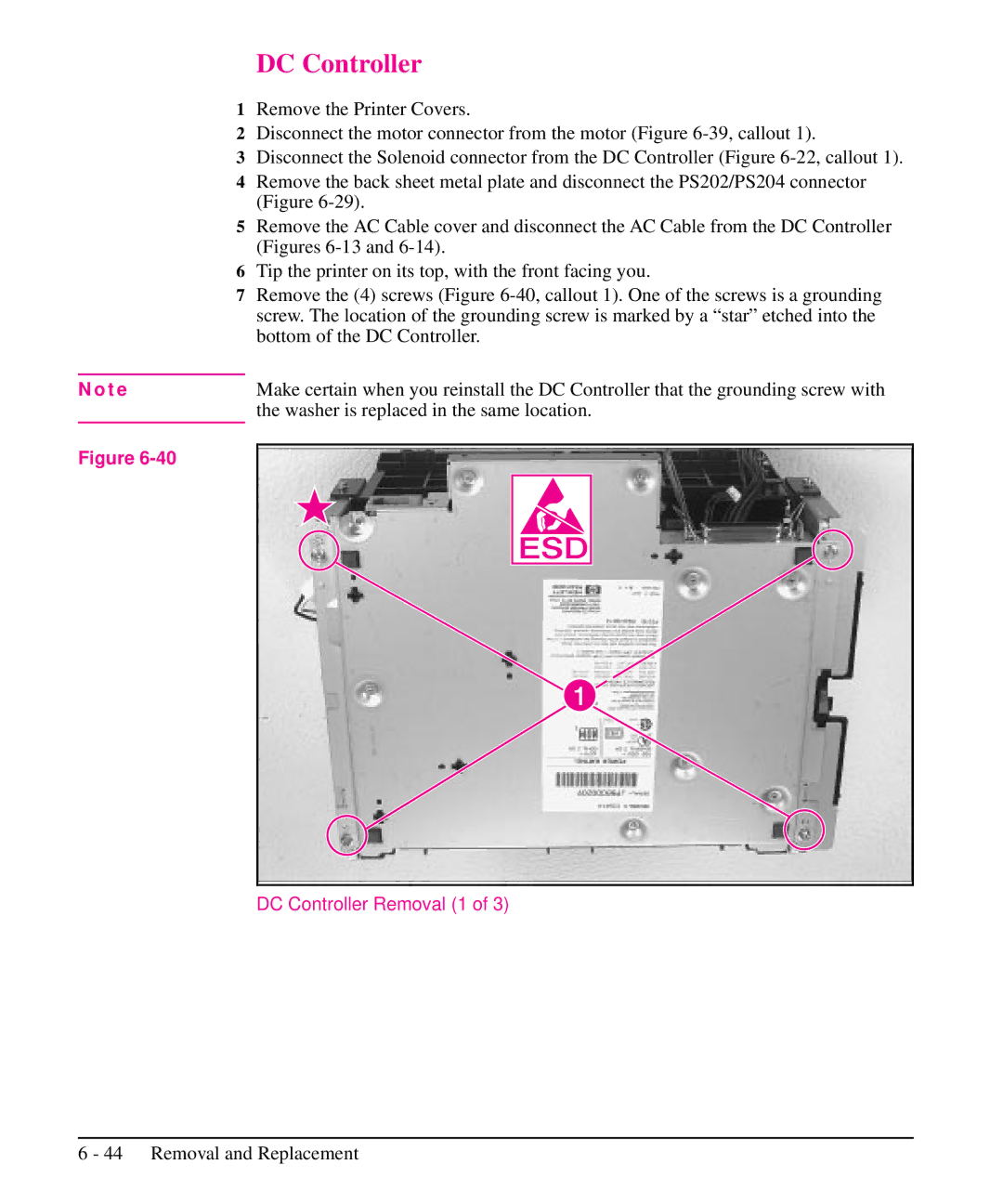
7Remove the (4) screws (Figure
N o t e | Make certain when you reinstall the DC Controller that the grounding screw with | |||
| the washer is replaced in the same location. | |||
Figure |
|
|
|
|
|
|
|
| |
|
|
|
|
|
|
|
|
|
|
|
|
|
|
|
|
|
|
|
|