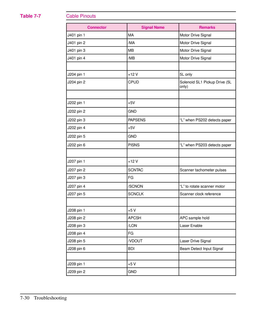
Table | Cable Pinouts |
|
|
|
|
|
|
| Connector | Signal Name | Remarks |
| J401 pin 1 | MA | Motor Drive Signal |
|
|
|
|
| J401 pin 2 | /MA | Motor Drive Signal |
|
|
|
|
| J401 pin 3 | MB | Motor Drive Signal |
|
|
|
|
| J401 pin 4 | /MB | Motor Drive Signal |
|
|
|
|
|
|
|
|
| J204 pin 1 | +12 V | 5L only |
|
|
|
|
| J204 pin 2 | CPUD | Solenoid SL1 Pickup Drive (5L |
|
|
| only) |
|
|
|
|
|
|
|
|
| J202 pin 1 | +5V |
|
|
|
|
|
| J202 pin 2 | GND |
|
|
|
|
|
| J202 pin 3 | PAPSENS | “L” when PS202 detects paper |
|
|
|
|
| J202 pin 4 | +5V |
|
|
|
|
|
| J202 pin 5 | GND |
|
|
|
|
|
| J202 pin 6 | PISNS | “L” when PS203 detects paper |
|
|
|
|
|
|
|
|
| J207 pin 1 | +12 V |
|
|
|
|
|
| J207 pin 2 | SCNTAC | Scanner tachometer pulses |
|
|
|
|
| J207 pin 3 | FG |
|
|
|
|
|
| J207 pin 4 | /SCNON | “L” to rotate scanner motor |
|
|
|
|
| J207 pin 5 | SCNCLK | Scanner clock reference |
|
|
|
|
|
|
|
|
| J208 pin 1 | +5 V |
|
|
|
|
|
| J208 pin 2 | APCSH | APC sample hold |
|
|
|
|
| J208 pin 3 | /LON | Laser Enable |
|
|
|
|
| J208 pin 4 | FG |
|
|
|
|
|
| J208 pin 5 | /VDOUT | Laser Drive Signal |
|
|
|
|
| J208 pin 6 | BDI | Beam Detect Input Signal |
|
|
|
|
|
|
|
|
| J209 pin 1 | +5 V |
|
|
|
|
|
| J209 pin 2 | GND |
|
|
|
|
|