Table |
| Printer Status Messages (Continued 2 of 2) | |||
|
|
|
|
|
|
|
| LEDs |
| Description | Recommended Action |
|
|
|
|
|
|
|
|
| Sleep Mode | If the printer’s LEDs remain off: | |
|
|
|
|
| 1. The printer is in Sleep Mode. Press the Front Panel |
|
|
|
|
| |
|
|
|
|
| Button or open the EP Door. |
|
|
|
|
| 2. Power is not supplied to the printer. Check power |
|
|
|
|
| |
|
|
|
|
| |
|
|
|
|
| cord connections and the power source. |
|
|
|
|
| |
|
|
|
|
| 3. Print an engine test to determine if the print engine |
|
|
|
|
| |
|
|
|
|
| |
|
|
|
|
| is functional. If the test is successful, replace the |
|
|
|
|
| Formatter PCA. |
|
|
|
|
| 4. See the General Troubleshooting Flowchart earlier |
|
|
|
|
| in this chapter. |
|
|
|
|
|
|
|
|
|
|
| Occasionally you may add paper, close the printer door, add the toner cartridge, and |
|
|
|
|
| clear a paper jam, only to find that the printer still displays an error message. If this |
|
|
|
|
| happens, troubleshoot using Table |
|
|
|
|
|
|
N o t e |
|
| If the error appears and persists only after you attempt to print a page, verify that | ||
|
|
|
|
| the motor is functioning. (See “Printing an Engine Test” later in this chapter.) |
Table |
|
|
| ||
|
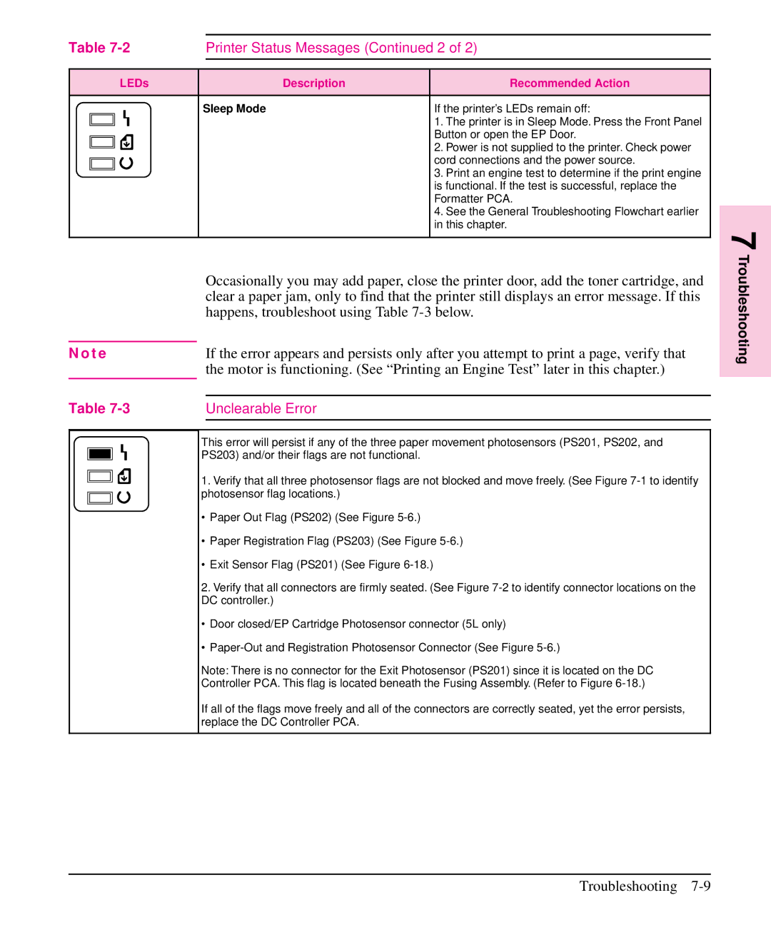
| Unclearable Error | |||
|
|
|
|
|
|
|
|
|
|
|
|
|
|
|
| This error will persist if any of the three paper movement photosensors (PS201, PS202, and | |
|
|
|
| PS203) and/or their flags are not functional. | |
|
|
|
| ||
1. Verify that all three photosensor flags are not blocked and move freely. (See Figure
∙Paper Out Flag (PS202) (See Figure
∙Paper Registration Flag (PS203) (See Figure
∙Exit Sensor Flag (PS201) (See Figure
2.Verify that all connectors are firmly seated. (See Figure
∙Door closed/EP Cartridge Photosensor connector (5L only)
∙
Note: There is no connector for the Exit Photosensor (PS201) since it is located on the DC
Controller PCA. This flag is located beneath the Fusing Assembly. (Refer to Figure
If all of the flags move freely and all of the connectors are correctly seated, yet the error persists, replace the DC Controller PCA.
7 Troubleshooting