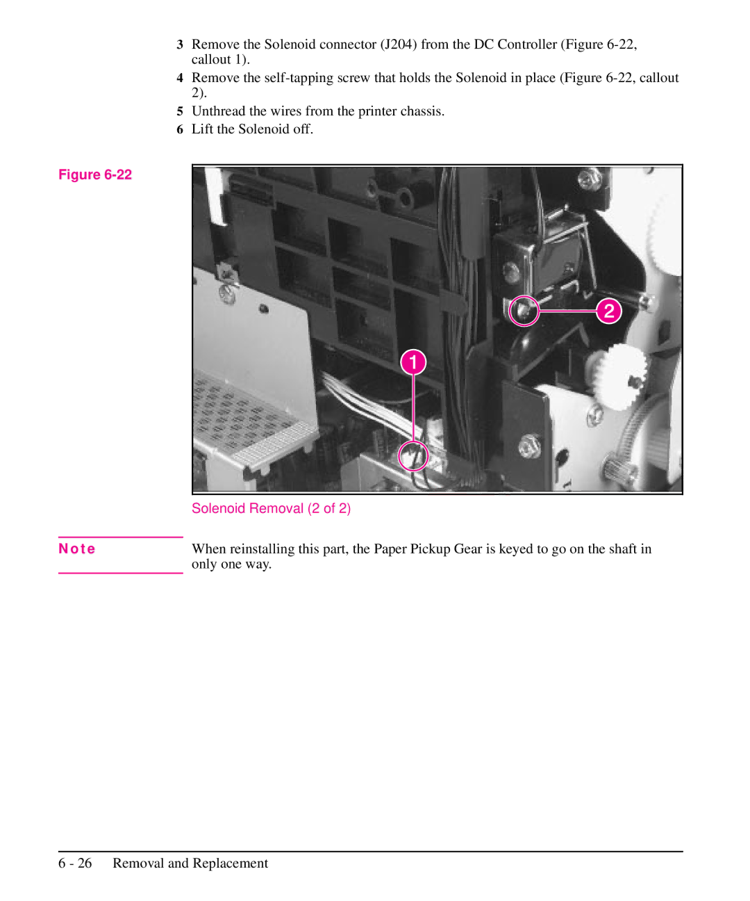
3Remove the Solenoid connector (J204) from the DC Controller (Figure
4Remove the
5Unthread the wires from the printer chassis.
6Lift the Solenoid off.
Figure
| Solenoid Removal (2 of 2) |
|
|
N o t e | When reinstalling this part, the Paper Pickup Gear is keyed to go on the shaft in |
| only one way. |