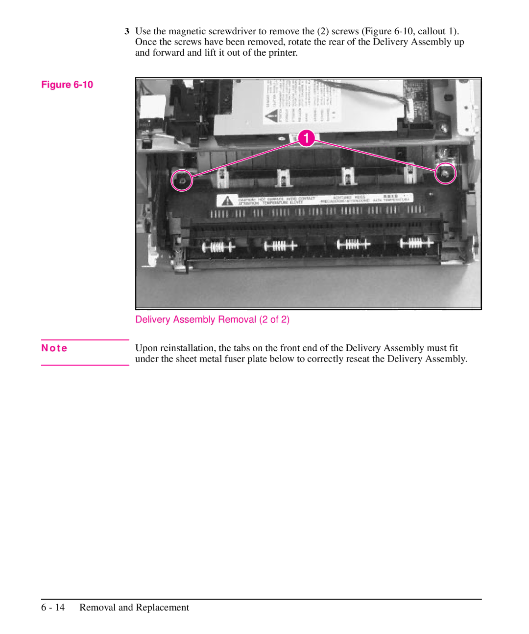
3Use the magnetic screwdriver to remove the (2) screws (Figure
Figure
| Delivery Assembly Removal (2 of 2) |
|
|
N o t e | Upon reinstallation, the tabs on the front end of the Delivery Assembly must fit |
| under the sheet metal fuser plate below to correctly reseat the Delivery Assembly. |