Manuals
/
HP
/
Computer Equipment
/
Personal Computer
HP
8300 D0K72US#ABA, 8300 C5J37AWABA
manual
Rotate the panel out and off of the computer
Models:
8300 C5J37AWABA
8300 D0K72US#ABA
1
85
165
165
Download
165 pages
39.51 Kb
82
83
84
85
86
87
88
89
Specs
Error messages
Maintenance
VGA Configuration
Solving general problems
Accessing disk image ISO files
Computer Setup F10 Utility
Cables and connectors
Updating Smbios Information
Replacing the battery
Page 85
Image 85
7.
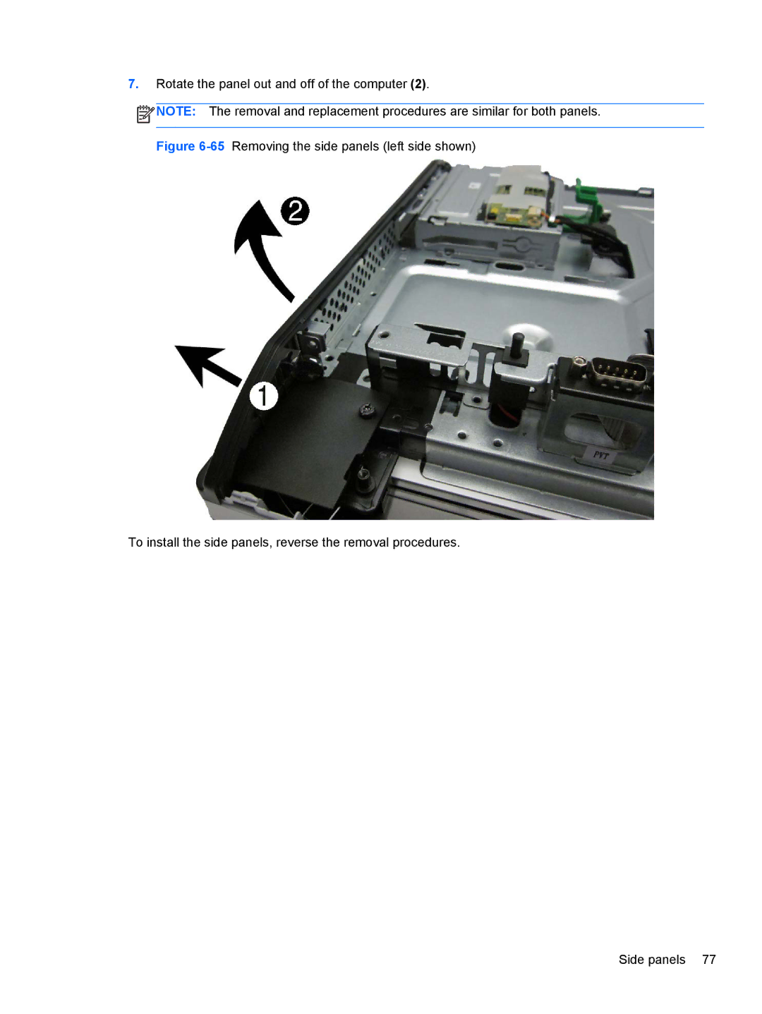
Rotate the panel out and off of the computer
(2)
.
NOTE:
The removal and replacement procedures are similar for both panels.
Figure
6-65
Removing the side panels (left side shown)
To install the side panels, reverse the removal procedures.
Side panels 77
Page 84
Page 86
Page 85
Image 85
Page 84
Page 86
Contents
Maintenance & Service Guide
Maintenance & Service Guide
Iii
About This Book
Iv About This Book
Table of contents
Removal and Replacement Procedures All-in One AIO Chassis
105
103
107
108
Models 153 154
Interpreting Post diagnostic front panel LEDs 143
Viii
Overview
Product Features
Page
1Front components
Front components
Component
2Side components
Side components
Rear components
Rear components
3Rear components
Installing the operating system
Installing and customizing the software
Downloading Microsoft Windows updates
Accessing disk image ISO files
Installing or upgrading device drivers Windows systems
Protecting the software
Computer Setup F10 utilities
Computer Setup F10 Utility
Using Computer Setup F10 utilities
Computer Setup F10 Utility
Computer Setup-File
1Computer Setup-File
2Computer Setup-Storage
Computer Setup-Storage
3Computer Setup-Security
Computer Setup-Security
Master Boot Record
Network Boot
Slot Security
System IDs
DriveLock Security
System Security
4Computer Setup-Power
Computer Setup-Power
5Computer Setup-Advanced
Computer Setup-Advanced
Option Heading Power-On Options
Bios Power-On
Bus Options
VGA Configuration
Device Options
Operations
Serial ATA Hard Drive Characteristics
Serial ATA Sata Drive Guidelines and Features
Sata Hard Drives
Sata Hard Drive Cables
Hard Drive Capacities
Smart ATA Drives
Smart ATA Drives
Routine Care and Disassembly Preparation
Generating static
Electrostatic discharge information
Preventing electrostatic damage to equipment
Relative Humidity Event 55% 40% 10%
Grounding the work area
Personal grounding methods and equipment
Recommended materials and equipment
Static Shielding Protection Levels
Operating Guidelines
Cleaning the computer case
General cleaning safety precautions
Cleaning the keyboard
Routine Care
Cleaning the display
Service Considerations
Cleaning the mouse
Tools and software requirements
Lithium coin cell battery
Cables and connectors
Hard drives
Preparing to disassemble the computer
Removal and Replacement Procedures All-in One AIO Chassis
Adjusting the tilt/swivel base
Height adjustable/recline stand optional
Page
Cable management cover
Removing the rear port cover
Synchronizing the optional wireless keyboard or mouse
Installing an access panel security screw
Page
Access panel
Page
Stand
Page
Lower panel
17Lower panel location To remove the access panel
Metal plate is located under the stand
Metal plate
Page
Replacing drives
Remove the access panel see Access panel on Replacing drives
Page
Page
Page
28Optical drive location
Replacing the optical disc drive
Page
Page
Memory
Location System Board Label Channel
1Identifying Sodimm locations
Page
Replacing the battery
Page
39Serial port location To remove the serial port
Serial port
Page
Webcam module
Remove the access panel see Access panel on Webcam module
Page
Page
45Converter board location To remove the converter board
Converter board
Page
Inch
Touch sensor board
Page
Graphics heat sink
Heat sinks Graphics board and processor
To remove the heat sink
Processor heat sink model
Processor heat sink model
Lift the heat sink assembly from the computer
Processor
MSATA Solid-State Drive
To remove the mSATA SSD
Wlan module
Page
Page
59Graphics board location To remove the graphics board
Graphics board
Page
61Speaker location To remove the speakers
Speakers
Fan
64Side panel locations To remove the side panels
Side panels
Rotate the panel out and off of the computer
66Power supply location To remove the power supply
Power supply
68Removing the power supply Power supply
Page
Remove the processor see Processor on
System board
Page
Page
Page
Page
Setup Field Name Comment Label
Updating Smbios Information
Card reader board
Page
Power button board
Page
Page
Front bezel
Page
Right 4 screws Bottom 2 screw
Antenna
Page
Display panel
To install the antenna, reverse the removal procedures
Page
86Display panel screw locations 6300 models CMI panel
Page
Page
Inch
Hood sensor
Page
Hard drive and optical drive cables and connectors
Page
Safety and comfort
Troubleshooting Without Diagnostics
Safety and comfort
Troubleshooting Without Diagnostics
Solving general problems
1Solving general problems
Computer date and time display is incorrect Cause Solution
There is no sound or sound volume is too low Cause Solution
Solving general problems
Poor performance is experienced Cause Solution
Cause Solution
Solving hard drive problems
Solving power problems
Solving power problems
2Solving power problems
Drive not found identified Cause Solution
Disk transaction problem Cause Solution
Power-On
Advanced Power-On Options
Computer will not boot from hard drive Cause Solution
Solving hard drive problems
Storage Boot Order
Computer seems to be locked up Cause Solution
4Solving media card reader problems
Solving media card reader problems
Can not write to the media card Cause
Solving display problems
Solving display problems
5Solving display problems
Blank screen no video Cause Solution
Out of Range displays on screen Cause Solution
Solving audio problems
Solving audio problems
6Solving audio problems
Sound from headphones is not clear or muffled Cause
Enable digital CD audio for this CD-ROM device is
Advanced Device Options Internal Speaker
Line-in jack is not functioning properly Cause
Solving printer problems
Solving printer problems
7Solving printer problems
8Solving keyboard problems
Solving keyboard and mouse problems
Printer prints garbled information Cause Solution
Printer is offline Cause Solution
9Solving Mouse Problems
Solving keyboard and mouse problems
10Solving hardware installation problems
Solving hardware installation problems
Computer will not start Cause Solution
Security USB Security
Solving hardware installation problems
11Solving network problems
Solving network problems
Diagnostics reports a failure Cause Solution
Solving network problems
12Solving memory problems
Solving memory problems
New network card will not boot Cause
Out of memory error Cause Solution
Solving memory problems
Memory count during Post is wrong Cause Solution
Insufficient memory error during operation Cause Solution
Solving CD-ROM and DVD problems
Solving processor problems
13Solving processor problems
14Solving CD-ROM and DVD problems
Movie will not play in the DVD drive Cause Solution
Solving CD-ROM and DVD problems
15Solving USB flash drive problems
Solving USB flash drive problems
Cannot eject compact disc tray-load unit Cause
Solving internet access problems
Solving internet access problems
16Solving internet access problems
Click Network and Internet
Unable to connect to the Internet Cause
Click Internet Options
Click on Hardware and Sound
Solving software problems
Solving software problems
17Solving software problems
Post Error Messages
Post Numeric Codes and Text Messages
Post Numeric Codes and Text Messages
1Numeric Codes and Text Messages
Control panel message Description Recommended action
Post Error Messages
Verify monitor is attached and turned
Options Sata Emulation to IDE,
Test under Storage DPS Self-test
Select File Save Changes and Exit
Security Drivelock Security. For each
Post Numeric Codes and Text Messages
Bios
Occurred prior to the ME firmware update
Post Error Messages
Interpreting Post diagnostic front panel LEDs
Interpreting Post diagnostic front panel LEDs
2Diagnostic front panel LEDs and audible codes
Activity
Desktop Management Guide for more
Interpreting Post diagnostic front panel LEDs
Cmos
Password Security and Resetting
Establishing a Setup or Power-on password
Establishing a Setup or Power-on password
Resetting the Setup and Power-on password
Clearing and resetting the Cmos
Cmos button
Locate, press, and hold the Cmos button in for five seconds
Japanese Power Cord Requirements
Power Cord Set Requirements
General requirements
Country-specific requirements
Appendix a Power Cord Set Requirements
Country Accrediting Agency
Table B-1Specifications
Specifications
Models
Models
Table B-2Specifications
Appendix B Specifications
Cmos
Index
Sata
Top
Page
Image
Contents