Installation, User’s, and Maintenance Guide
Page
Installation, User’s, and Maintenance Guide
Page
Iii
Safety
To Connect To Disconnect
IEC 825-11993 Cenelec EN 60
Statement
Safety
Page
Contents
Operating the storage server
Cabling the storage server
Appendix B. Rack mounting template
Installing and replacing components
131
Figures
Page
Tables
Page
FAStT product renaming
About this document
Who should read this document
Xvii
How this document is organized
Figures used in this document
DS4000 installation process overview
DS4500 storage server library
DS4000 Storage Server publications
About this document
DS4400 storage server library
DS4100 storage server library
DS4300 storage server library
Page
DS4000-related hardware publications
DS4000 Storage Manager Version 9 publications
Power
Using the documentation
Getting information, help, and service
Before you call
Web sites
Fire suppression systems
Software service and support
Hardware service and support
How to send your comments
Page
About the DS4100 base storage server
Introduction
Overview
About the DS4100 single-controller storage server
Sata defined
Product updates
Fibre channel defined
Features at a glance
Features at a glance
Hardware
Inventory checklist
Clustering support
Software and documentation
Best practices guidelines
Storage server components
Hot-swap drive bays
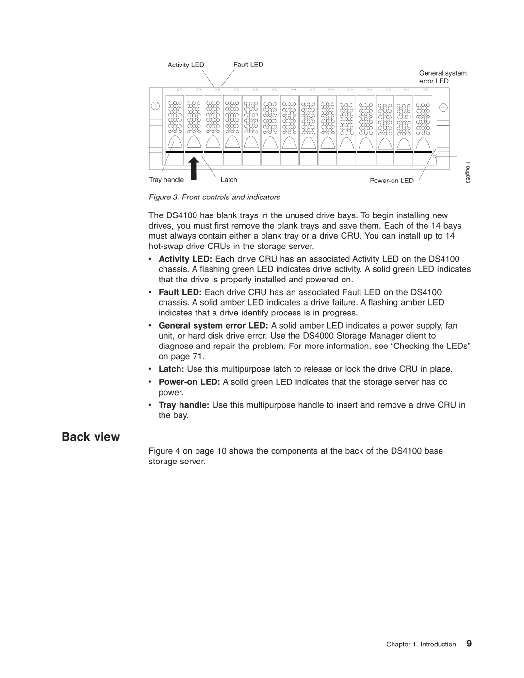
Front controls and indicators
Back view
Front controls and indicators
Hot-swap fans
RAID controller
Hot-swap power supplies
Interface ports and switches
Host ports
Server ID switch enclosure ID switch
Ethernet port
Expansion port
Storage server operating environment
Gbps/2 Gbps switch
DS4100 specifications
Low Range High Range
Heat output, airflow, and cooling
Hot aisle
Use safe practices when lifting
Installing the storage server
Installation overview
Handling static-sensitive devices
Preparing for installation
Preparing the rack cabinet
Preparing the site
Rack mounting template
Installing the DS4100
Front
Rear
Installing the support rails
Rack flange type Pins to remove
Alignment pins with and without spacers
Installing the support rails
Removing a RAID controller
Removing the CRUs
Removing a power supply
Removing a fan
Removing a hard disk drive
Installing the DS4100 into a rack cabinet
Replacing the DS4100 CRUs
Installing the DS4100
Replacing a RAID controller
Replacing a fan
Replacing a hard disk drive
Setting the interface options
Server ID enclosure ID settings
Fibre channel loop and ID settings
Storage subsystem management methods
Storage server speed settings
Configuring the storage subsystem
Direct out-of-band management method
Fibre channel connections
Fibre channel loop configurations
Redundant host and drive loops
Switch
DS4100 DS4000 EXP100 Expansion unit
Example of a two-cluster configuration base storage server
Host Server
Installing the storage subsystem configuration
Installing the storage server
Page
Handling fiber-optic cables
Cabling the storage server
Working with SFPs and fiber-optic cables
Installing SFP modules
Connect a fibre channel cable
Removing SFP modules
Installing fiber-optic cables
Removing caps from fiber-optic cables
Using LC-LC fibre-channel cables
LC-LC fibre-channel cable
Connecting an LC-LC cable to an SFP module
Removing fiber-optic cable protective caps
Removing an LC-LC fibre-channel cable
LC-LC fibre-channel cable lever and latches
Using LC-SC fibre-channel cable adapters
LC-SC fibre-channel cable adapter
Connecting an LC-SC cable adapter to a device
Removing the LC-SC cable adapter protective caps
Removing an LC-LC cable from an LC-SC cable adapter
Connecting hosts to a DS4100 base storage server
Connecting hosts to the RAID controllers
Location of host cables base storage server
Connecting secondary interface cables
Ethernet and serial port locations
Connecting expansion units base storage server only
Page
Adding an expansion unit
DS4000 EXP100 redundant loop configuration
Power cord locations
Power cabling
Installing the DS4000 Storage Manager client
Cabling the storage server
Page
Turning the storage server on and off
Operating the storage server
Turning on the storage server
Turning off the storage server
Restoring power after an unexpected shutdown
Performing an emergency shutdown
Restoring power after an emergency shutdown
Restoring power after an over-temperature shutdown
Monitoring status through software
Checking the LEDs
Flashing every 5 seconds The drive has not
Color Operating states1
Color
Fault
Icon
If there is no Ethernet connection Both
If the Ethernet connection is 10BASE-T
If the Ethernet connection is
Color Operating states
Cache memory and RAID controller battery
Cache memory
Cache active LED
RAID controller cache battery
Battery LED
Page
Working with hot-swap hard disk drives
Installing and replacing components
LED state Descriptions
Installing hot-swap hard disk drives
Hot-swap hard disk drive LEDs
Drive CRU handle
Replacing hot-swap hard disk drives
Replacing all the drives at the same time
Upgrading drives
Adding larger-capacity drives
Replacing the drives one at a time
Replacing all drives at the same time
Installing and replacing components
Replacing the drives one at a time
Installing and replacing components
Working with hot-swap cooling fans
Fault LEDs
Fan CRUs
Latches and handles
Working with power supplies
Levers
Power LED
AC power switches
AC power connectors
Removing a power supply
Strain-relief clamp
DS4100 single-controller storage server only
Lever for power supply removal
Installing a power supply
Connecting the power cord to the AC power connector
Working with RAID controllers
Cache battery is not included with the controller CRU
RAID controller levers and labels
Replacing a RAID controller
To replace a RAID controller, perform the following steps
Unlocking the SFP module latch plastic variety
Pull-rings for removing a controller
Removing the controller battery
Installing and replacing components
Page
Installing and replacing components
Page
Replacing the battery in the RAID controller
Page
Contains Sealed Lead Battery Must be Recycled
Install the RAID controller, as shown in Figure
Installing SFPs and fiber-optic cables
Cabling the DS4100 to a redundant loop
Using the diagnostic hardware
Hardware maintenance
Solving problems
General checkout
Symptom-to-FRU index
Hardware maintenance
Supplies. If applicable, check
Parts listing
FRU P/N
Index DS4100 storage server
FRU P/N
Page
Identification numbers
Installed device records
Appendix A. Records
Page
Appendix B. Rack mounting template
Front
Appendix B. Rack mounting template
Page
125
Appendix C. Power cords
Islands, Cyprus, Dominica, Gambia, Ghana, Grenada
127
Trademarks
Federal Communications Commission FCC statement
Important notes
Electronic emission notices
Avis de conformité à la réglementation d’Industrie Canada
European Union EMC Directive conformance statement
Page
Abstract Windowing Toolkit AWT. a Java graphical
Glossary
See also
DMA. See direct memory access
Auto-volume transfer/auto-disk transfer AVT/ADT
Fibre Channel-Arbitrated Loop FC-AL. See
Expansion port Eport. a port that connects
Host computer. See host
GUI. See graphical user interface HBA. See host bus adapter
MIB. See management information base
Peripheral component interconnect local bus PCI
ODM. See Object Data Manager
Simple Network Management Protocol SNMP.
ROM. See read-only memory
Terminate and stay resident program TSR
SNMP. See Simple Network Management Protocol and SNMPv1
Transmission Control Protocol/Internet Protocol
Transmission Control Protocol TCP. a
Page
141
Index
129 Federal Communications Commission FCC
Size Speed settings, setting Tray handle Unpacking Weight
Gbic
Please tell us how we can improve this book
Readers’ Comments We’d Like to Hear from You
How satisfied are you that the information in this book is
Business Reply Mail
Page
Part Number 25R0314