SIGNAL DESCRIPTIONS
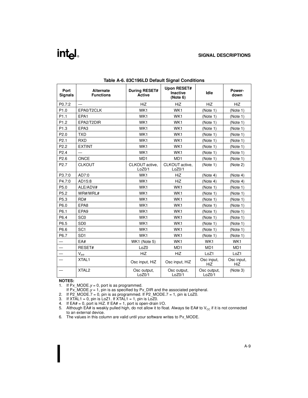
Table A-6. 83C196LD Default Signal Conditions
Port | Alternate | During RESET# | Upon RESET# |
| Power- | |
Inactive | Idle | |||||
Signals | Functions | Active | down | |||
(Note 6) |
| |||||
|
|
|
|
| ||
|
|
|
|
|
| |
P0.7:2 | — | HiZ | HiZ | HiZ | HiZ | |
P1.0 | EPA0/T2CLK | WK1 | WK1 | (Note 1) | (Note 1) | |
P1.1 | EPA1 | WK1 | WK1 | (Note 1) | (Note 1) | |
P1.2 | EPA2/T2DIR | WK1 | WK1 | (Note 1) | (Note 1) | |
P1.3 | EPA3 | WK1 | WK1 | (Note 1) | (Note 1) | |
P2.0 | TXD | WK1 | WK1 | (Note 1) | (Note 1) | |
P2.1 | RXD | WK1 | WK1 | (Note 1) | (Note 1) | |
P2.2 | EXTINT | WK1 | WK1 | (Note 1) | (Note 1) | |
P2.4 | — | WK1 | WK1 | (Note 1) | (Note 1) | |
P2.6 | ONCE | MD1 | MD1 | (Note 1) | (Note 1) | |
P2.7 | CLKOUT | CLKOUT active, | CLKOUT active, | (Note 1) | (Note 2) | |
|
| LoZ0/1 | LoZ0/1 |
|
| |
P3.7:0 | AD7:0 | WK1 | HiZ | (Note 4) | (Note 4) | |
P4.7:0 | AD15:8 | WK1 | HiZ | (Note 4) | (Note 4) | |
P5.0 | ALE/ADV# | WK1 | WK1 | (Note 1) | (Note 1) | |
P5.2 | WR#/WRL# | WK1 | WK1 | (Note 1) | (Note 1) | |
P5.3 | RD# | WK1 | WK1 | (Note 1) | (Note 1) | |
P6.0 | EPA8 | WK1 | WK1 | (Note 1) | (Note 1) | |
P6.1 | EPA9 | WK1 | WK1 | (Note 1) | (Note 1) | |
P6.4 | SC0 | WK1 | WK1 | (Note 1) | (Note 1) | |
P6.5 | SD0 | WK1 | WK1 | (Note 1) | (Note 1) | |
P6.6 | SC1 | WK1 | WK1 | (Note 1) | (Note 1) | |
P6.7 | SD1 | WK1 | WK1 | (Note 1) | (Note 1) | |
— | EA# | WK1 (Note 5) | WK1 | WK1 | WK1 | |
— | RESET# | LoZ0 | MD1 | MD1 | MD1 | |
— | V PP | HiZ | HiZ | LoZ1 | LoZ1 | |
— | XTAL1 | Osc input, HiZ | Osc input, HiZ | Osc input, | Osc input, | |
|
| HiZ | HiZ | |||
|
|
|
| |||
— | XTAL2 | Osc output, | Osc output, | Osc output, | (Note 3) | |
|
| LoZ0/1 | LoZ0/1 | LoZ0/1 |
|
NOTES:
1.If Px_MODE.y = 0, port is as programmed.
If Px_MODE.y = 1, pin is as specified by Px_DIR and the associated peripheral.
2.If P2_MODE.7 = 0, pin is as programmed. If P2_MODE.7 = 1, pin is LoZ0.
3.If XTAL1 = 0, pin is LoZ1. If XTAL1 = 1, pin is LoZ0.
4.If EA# = 0, port is HiZ. If EA# = 1, port is
5.Although EA# is weakly pulled high, do not allow it to float. Always tie EA# to VCC if it is not connected to an external device.
6.The values in this column are valid until your software writes to Px_MODE.