J1850 COMMUNICATIONS CONTROLLER
1 | | | | | 1 | | | 64µS |
| | | 128µS | | | |
| | | | | |
| | | | or |
0 | | | | "passive 1" | 0 | | | "active 1" |
| | | | |
| | | | | | |
1 | | | | | 1 | | | 128µS |
| | | 64µS | | | |
| | | | |
| | | | or |
0 | | | | "passive 0" | 0 | | | "active 0" |
| | |
| | | | | | |
A5219-01
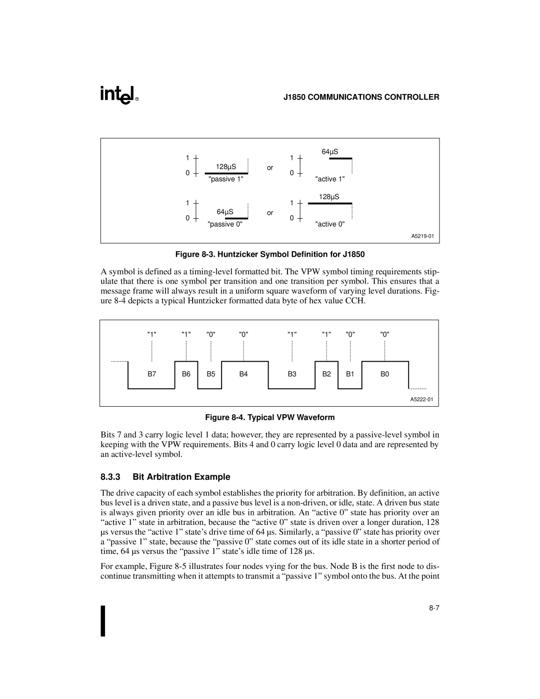
Figure 8-3. Huntzicker Symbol Definition for J1850
A symbol is defined as a timing-level formatted bit. The VPW symbol timing requirements stip- ulate that there is one symbol per transition and one transition per symbol. This ensures that a message frame will always result in a uniform square waveform of varying level durations. Fig- ure 8-4 depicts a typical Huntzicker formatted data byte of hex value CCH.
"1" | "1" | "0" | "0" | "1" | "1" | "0" | "0" |
B7 | B6 | B5 | B4 | B3 | B2 | B1 | B0 |
A5222-01
Figure 8-4. Typical VPW Waveform
Bits 7 and 3 carry logic level 1 data; however, they are represented by a passive-level symbol in keeping with the VPW requirements. Bits 4 and 0 carry logic level 0 data and are represented by an active-level symbol.
8.3.3Bit Arbitration Example
The drive capacity of each symbol establishes the priority for arbitration. By definition, an active bus level is a driven state, and a passive bus level is a non-driven, or idle, state. A driven bus state is always given priority over an idle bus in arbitration. An “active 0” state has priority over an “active 1” state in arbitration, because the “active 0” state is driven over a longer duration, 128 µs versus the “active 1” state’s drive time of 64 µs. Similarly, a “passive 0” state has priority over
a “passive 1” state, because the “passive 0” state comes out of its idle state in a shorter period of time, 64 µs versus the “passive 1” state’s idle time of 128 µs.
For example, Figure 8-5 illustrates four nodes vying for the bus. Node B is the first node to dis- continue transmitting when it attempts to transmit a “passive 1” symbol onto the bus. At the point
8-7

