MX240 Ethernet Services Router Hardware Guide
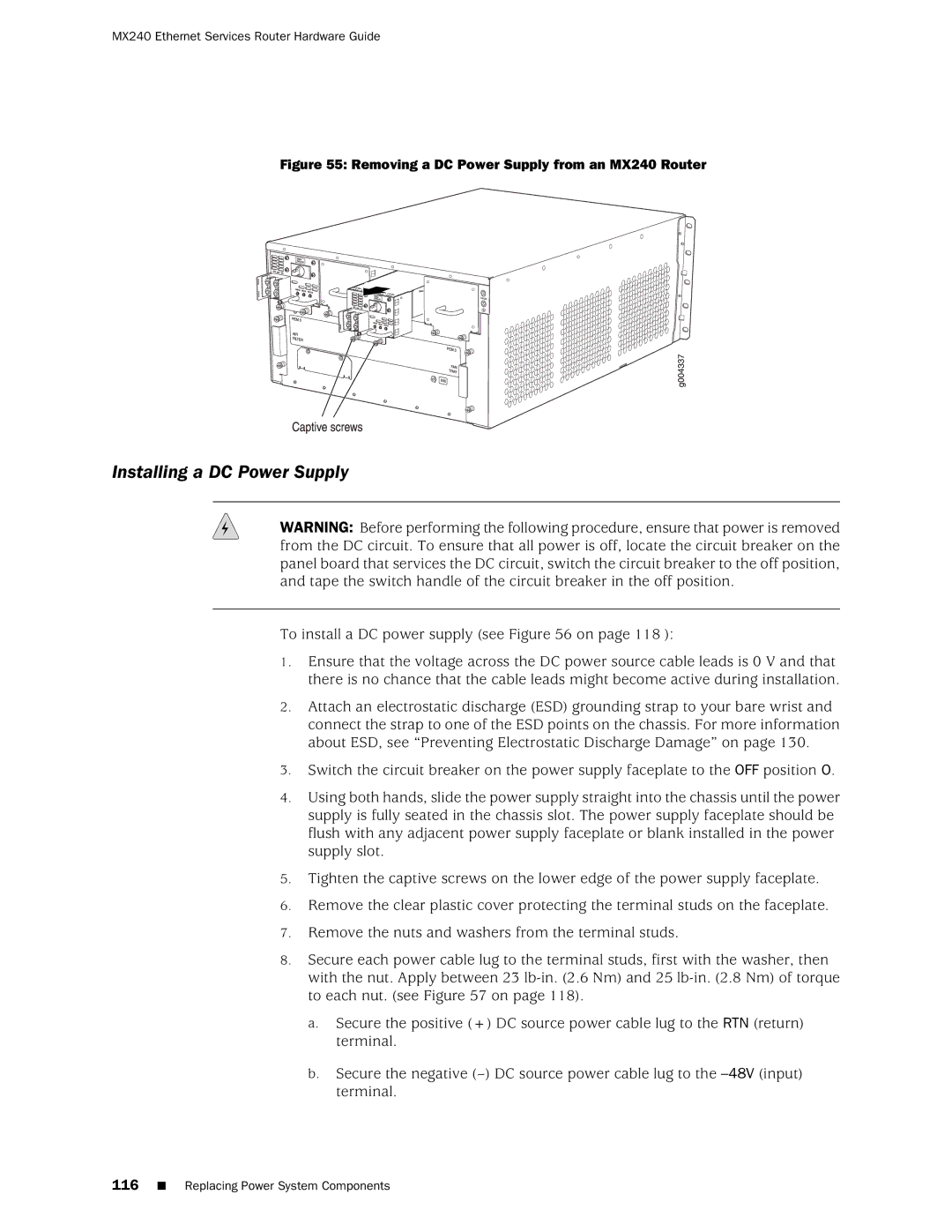
Figure 55: Removing a DC Power Supply from an MX240 Router
Installing a DC Power Supply
WARNING: Before performing the following procedure, ensure that power is removed from the DC circuit. To ensure that all power is off, locate the circuit breaker on the panel board that services the DC circuit, switch the circuit breaker to the off position, and tape the switch handle of the circuit breaker in the off position.
To install a DC power supply (see Figure 56 on page 118 ):
1.Ensure that the voltage across the DC power source cable leads is 0 V and that there is no chance that the cable leads might become active during installation.
2.Attach an electrostatic discharge (ESD) grounding strap to your bare wrist and connect the strap to one of the ESD points on the chassis. For more information about ESD, see “Preventing Electrostatic Discharge Damage” on page 130.
3.Switch the circuit breaker on the power supply faceplate to the OFF position O.
4.Using both hands, slide the power supply straight into the chassis until the power supply is fully seated in the chassis slot. The power supply faceplate should be flush with any adjacent power supply faceplate or blank installed in the power supply slot.
5.Tighten the captive screws on the lower edge of the power supply faceplate.
6.Remove the clear plastic cover protecting the terminal studs on the faceplate.
7.Remove the nuts and washers from the terminal studs.
8.Secure each power cable lug to the terminal studs, first with the washer, then with the nut. Apply between 23
a.Secure the positive (+) DC source power cable lug to the RTN (return) terminal.
b.Secure the negative
116■ Replacing Power System Components
