Chapter 2: Hardware Components
SCB Components
Each SCB consists of the following components:
■Chassis management Ethernet switch.
■I2C bus logic, used for
■Component redundancy circuitry.
■Control Board/Routing Engine mastership mechanism.
■Gigabit Ethernet switch that is connected to the embedded CPU complex on all components.
■Switch
■Control
■
■Ethernet
■Circuits for chassis management and control.
■Power circuits for the Routing Engine and SCB.
■
SCB LEDs
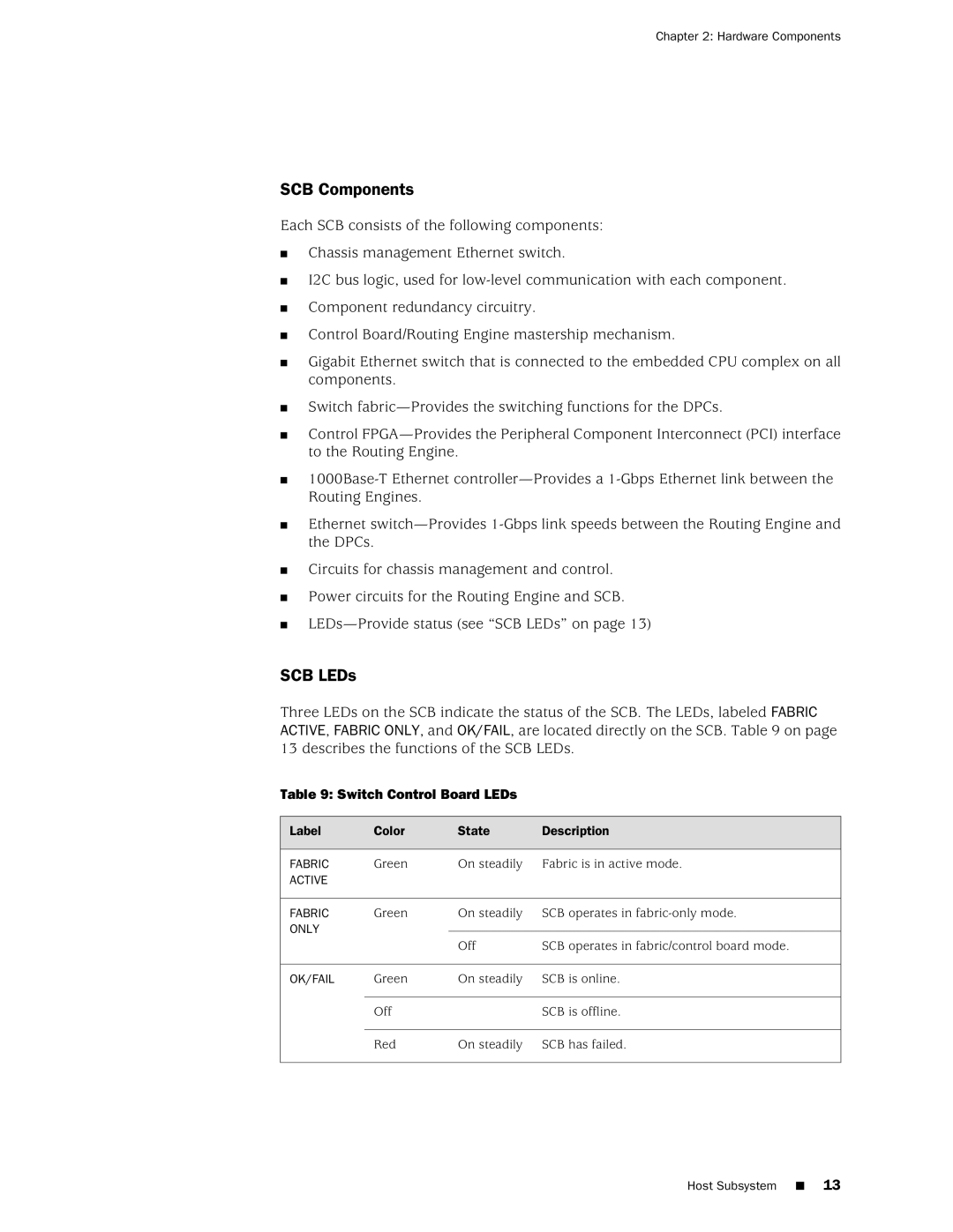
Three LEDs on the SCB indicate the status of the SCB. The LEDs, labeled FABRIC ACTIVE, FABRIC ONLY, and OK/FAIL, are located directly on the SCB. Table 9 on page 13 describes the functions of the SCB LEDs.
Table 9: Switch Control Board LEDs
Label | Color | State | Description |
FABRIC | Green | On steadily | Fabric is in active mode. |
ACTIVE |
|
|
|
FABRIC | Green | On steadily | SCB operates in |
ONLY |
|
|
|
|
| Off | SCB operates in fabric/control board mode. |
OK/FAIL | Green | On steadily | SCB is online. |
| Off |
| SCB is offline. |
| Red | On steadily | SCB has failed. |
Host Subsystem ■ 13