MX240 Ethernet Services Router Hardware Guide
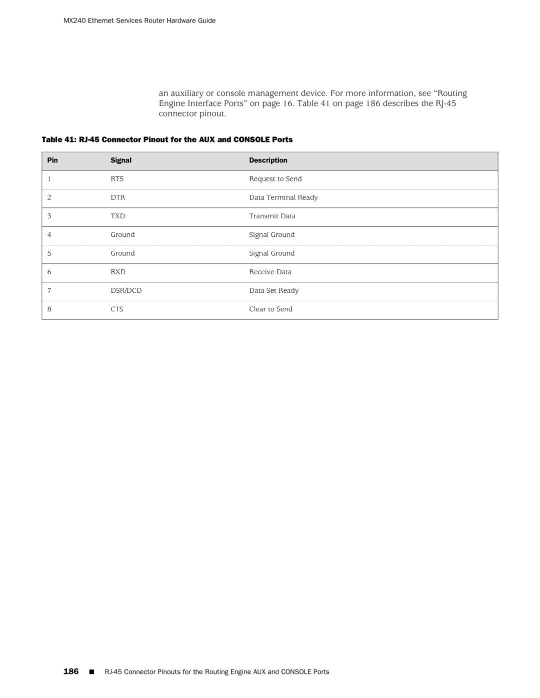
an auxiliary or console management device. For more information, see “Routing Engine Interface Ports” on page 16. Table 41 on page 186 describes the
Table 41: RJ-45 Connector Pinout for the AUX and CONSOLE Ports
Pin | Signal | Description |
1 | RTS | Request to Send |
2 | DTR | Data Terminal Ready |
3 | TXD | Transmit Data |
4 | Ground | Signal Ground |
5 | Ground | Signal Ground |
6 | RXD | Receive Data |
7 | DSR/DCD | Data Set Ready |
8 | CTS | Clear to Send |
186■