Chapter 2: Hardware Components
■
■
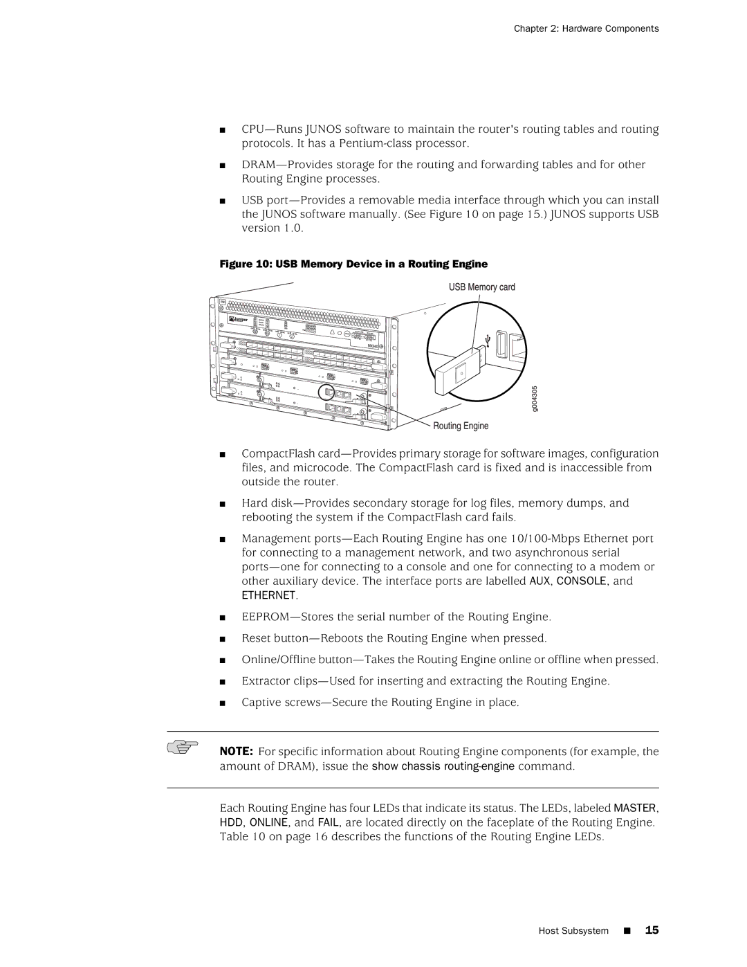
■USB
Figure 10: USB Memory Device in a Routing Engine
■CompactFlash
■Hard
■Management
ETHERNET.
■
■
■
■
■
Reset
Online/Offline
Extractor
Captive
NOTE: For specific information about Routing Engine components (for example, the amount of DRAM), issue the show chassis
Each Routing Engine has four LEDs that indicate its status. The LEDs, labeled MASTER, HDD, ONLINE, and FAIL, are located directly on the faceplate of the Routing Engine. Table 10 on page 16 describes the functions of the Routing Engine LEDs.
Host Subsystem ■ 15
