MX240 Ethernet Services Router Hardware Guide
DPC Components
Each DPC consists of the following components:
■DPC cover, which functions as a ground plane and a stiffener.
■Fabric interfaces.
■Two Gigabit Ethernet interfaces that allow control information, route information, and statistics to be sent between the Routing Engine and the CPU on the DPCs.
■Two interfaces from the SCBs that enable the DPCs to be powered on and controlled.
■Physical DPC connectors.
■Four Packet Forwarding Engines.
■Midplane connectors and power circuitry.
■Processor subsystem, which includes a
■Online
■LEDs on the
■LEDs on a
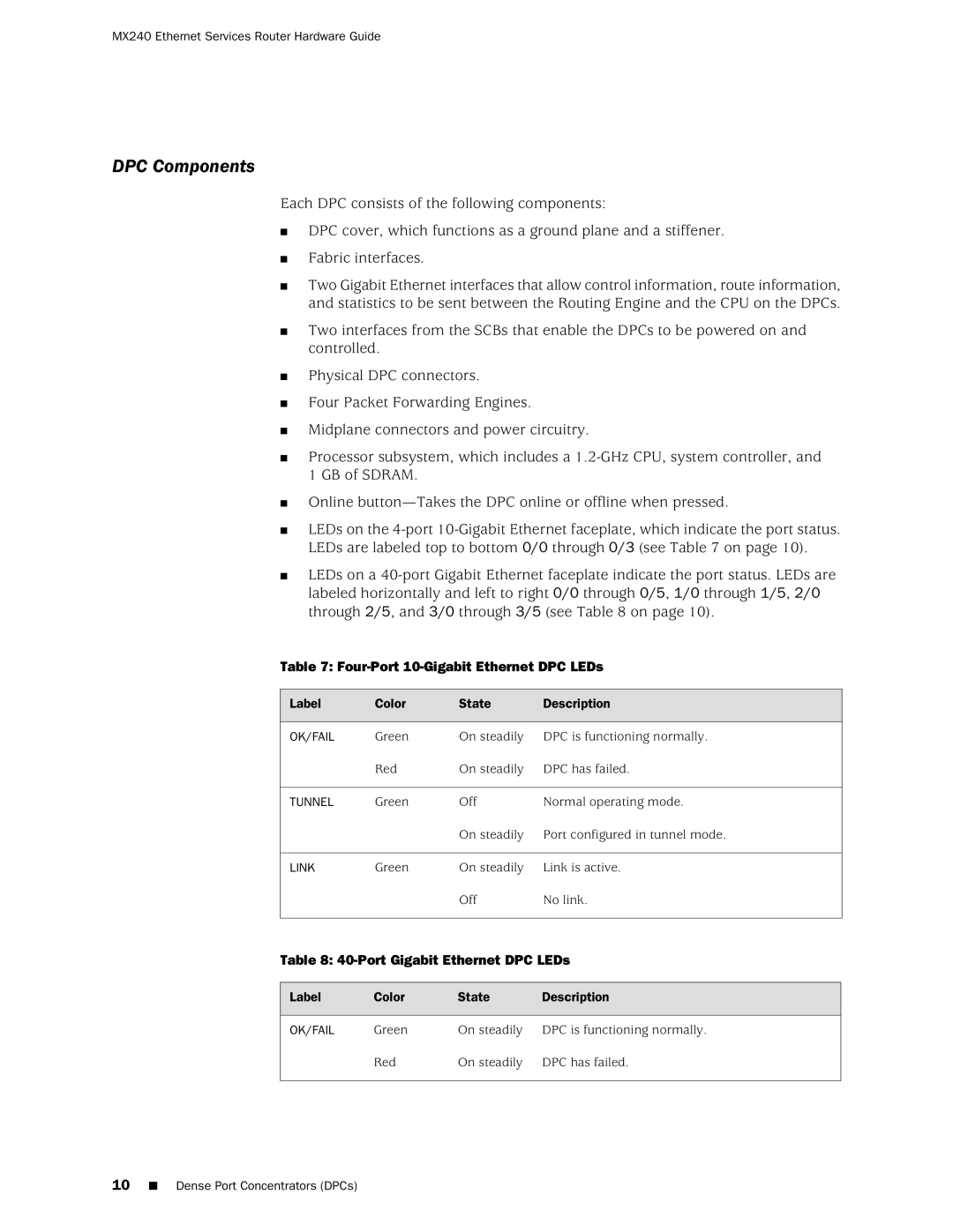
Table 7: Four-Port 10-Gigabit Ethernet DPC LEDs
Label | Color | State | Description |
OK/FAIL | Green | On steadily | DPC is functioning normally. |
| Red | On steadily | DPC has failed. |
TUNNEL | Green | Off | Normal operating mode. |
|
| On steadily | Port configured in tunnel mode. |
LINK | Green | On steadily | Link is active. |
|
| Off | No link. |
Table 8: 40-Port Gigabit Ethernet DPC LEDs
Label | Color | State | Description |
OK/FAIL | Green | On steadily | DPC is functioning normally. |
| Red | On steadily | DPC has failed. |
10■ Dense Port Concentrators (DPCs)