Defining the Control Room
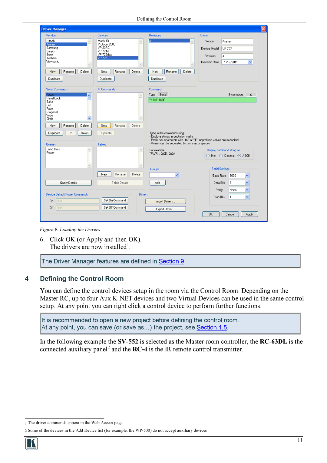
Figure 9: Loading the Drivers
6.Click OK (or Apply and then OK). The drivers are now installed1.
![]()
![]() The Driver Manager features are defined in Section 9
The Driver Manager features are defined in Section 9
4Defining the Control Room
You can define the control devices setup in the room via the Control Room. Depending on the Master RC, up to four Aux
It is recommended to open a new project before defining the control room.
At any point, you can save (or save as…) the project, see Section 1.5.
In the following example the
1 The driver commands appear in the Web Access page
2 Some of the devices in the Add Device list (for example, the
11