The Triggers
6.8.1Digital Input
The digital input reads the digital input of an external sensor device that is connected to the GPI/O port, and can be defined:
•With Pullup: the system can detect either a short circuit (activating the Hi to Lo trigger – closed circuit) or no short (activating the Lo to Hi trigger – open circuit) using the internal
For example, an alarm closing a circuit that activates a series of actions
•Without Pullup: the system detects the voltage levels and translates them to High or Low according to the user defined threshold levels.
For example, a high temperature alarm that exceeds the maximum voltage threshold
Setting the Digital Input
In this example, an alarm setting causes a short circuit, thus activating a trigger.
To set the trigger:
1.Define the GPI/O in the port manager.
Check Pullup for short circuit detection; the threshold is set automatically (skip step 2):
Do not check Pullup for voltage level detection; the threshold to be set by the user (proceed to step 2):
2.Define the GPI/O threshold (minimum from 0 and maximum up to 30V) according to the indication set by the device1.
Figure 87: GPI/O Threshold Window
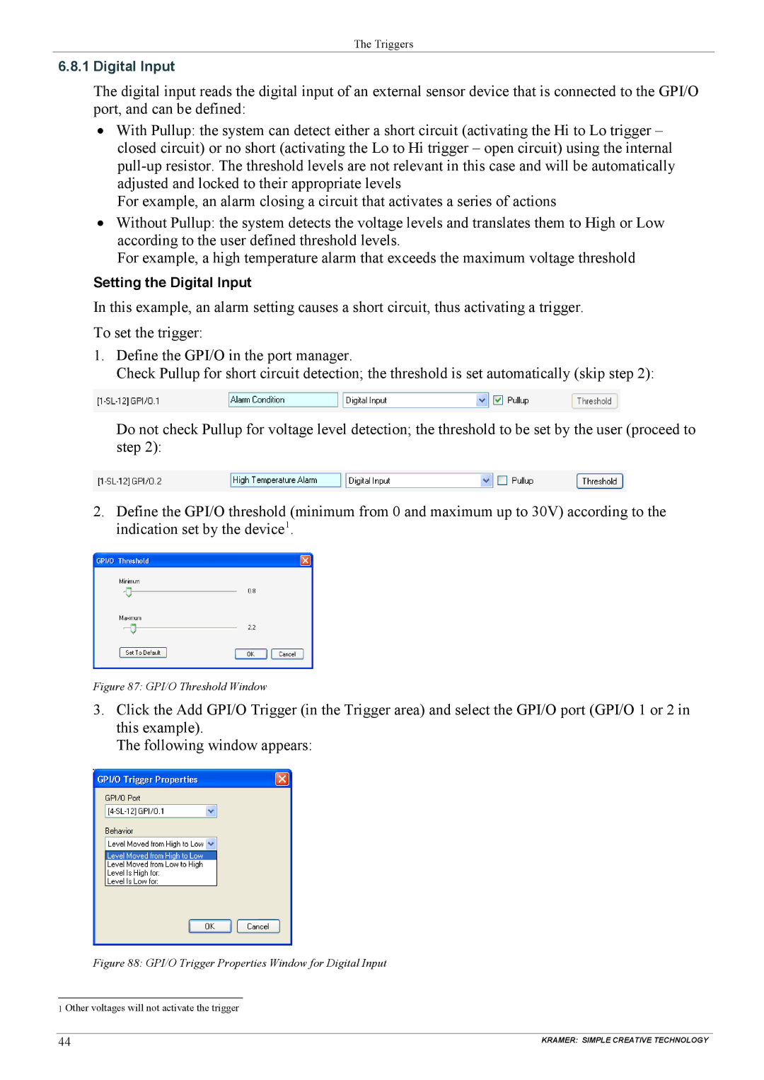
3.Click the Add GPI/O Trigger (in the Trigger area) and select the GPI/O port (GPI/O 1 or 2 in this example).
The following window appears:
Figure 88: GPI/O Trigger Properties Window for Digital Input
1 Other voltages will not activate the trigger
44 | KRAMER: SIMPLE CREATIVE TECHNOLOGY |