Defining the Control Room
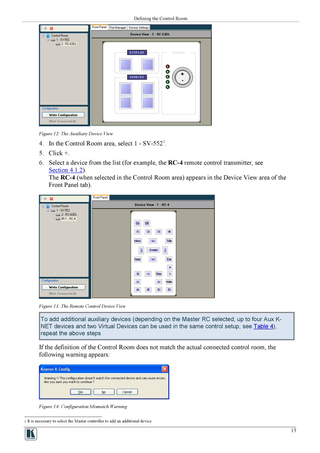
Figure 12: The Auxiliary Device View
4.In the Control Room area, select 1 -
5.Click +.
6.Select a device from the list (for example, the
The
Figure 13: The Remote Control Device View
To add additional auxiliary devices (depending on the Master RC selected, up to four Aux K- NET devices and two Virtual Devices can be used in the same control setup, see Table 4), repeat the above steps
If the definition of the Control Room does not match the actual connected control room, the following warning appears:
Figure 14: Configuration Mismatch Warning
1 It is necessary to select the Master controller to add an additional device
13