Defining the Control Room
Note: Be sure that your control room setup tree is correct before continuing with the configuration. If, at a later stage, an auxiliary
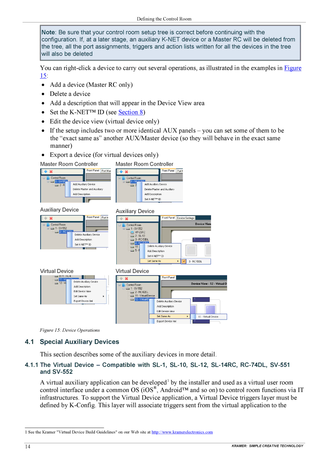
You can
15:
•Add a device (Master RC only)
•Delete a device
•Add a description that will appear in the Device View area
•Set the
•Edit the device view (virtual device only)
•If the setup includes two or more identical AUX panels – you can set some of them to be the “exact same as” another AUX/Master device (so they will behave in the exact same manner)
•Export a device (for virtual devices only)
Master Room Controller | Master Room Controller |
Auxiliary Device | Auxiliary Device |
Virtual Device | Virtual Device |
Figure 15: Device Operations
4.1 Special Auxiliary Devices
This section describes some of the auxiliary devices in more detail.
4.1.1The Virtual Device – Compatible with
A virtual auxiliary application can be developed1 by the installer and used as a virtual user room control interface under a common OS (iOS®, Android™ and so on) to control room functions via IT infrastructures. To support the Virtual Device application, a Virtual Device triggers layer must be defined by
1 See the Kramer "Virtual Device Build Guidelines" on our Web site at http://www.kramerelectronics.com
14 | KRAMER: SIMPLE CREATIVE TECHNOLOGY |