Tab Area Settings
Figure 29: Writing a Port Description
9.In the same way add a driver to each of the other ports.
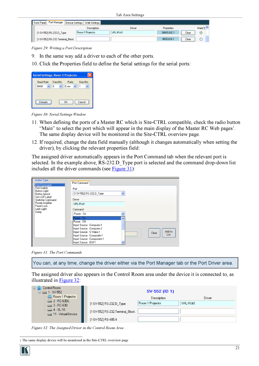
10.Click the Properties field to define the Serial settings for the serial ports:
Figure 30: Serial Settings Window
11.When defining the ports of a Master RC which is
12.If required, change the data field manually (although it changes automatically when setting the driver), by clicking the relevant properties field:
The assigned driver automatically appears in the Port Command tab when the relevant port is selected. In the example above,
Figure 31: The Port Commands
![]()
![]() You can, at any time, change the driver either via the Port Manager tab or the Port Driver area.
You can, at any time, change the driver either via the Port Manager tab or the Port Driver area.
The assigned driver also appears in the Control Room area under the device it is connected to, as illustrated in Figure 32:
Figure 32: The Assigned Driver in the Control Room Area
1 The same display device will be monitored in the
21