Rosemount 8732
Reference Manual
Table
Size Code | Line Size |
|
|
15F | 0.15 inch (4 mm) | 5 | 6.8 |
30F | 0.30 inch (8 mm) | 5 | 6.8 |
005 | 5 | 6.8 | |
010 | 1 inch (25 mm) | 10 | 13.6 |
015 | 11/2 inch (40 mm) | 15 | 20.5 |
020 | 2 inch (50 mm) | 25 | 34.1 |
030 | 3 inch (80 mm) | 40 | 54.6 |
040 | 4 inch (100 mm) | 30 | 40.1 |
060 | 6 inch (150 mm) | 50 | 68.2 |
080 | 8 inch (200 mm) | 70 | 81.9 |
INSTALLATION (SANITARY SENSOR)
Gaskets
Alignment and Bolting
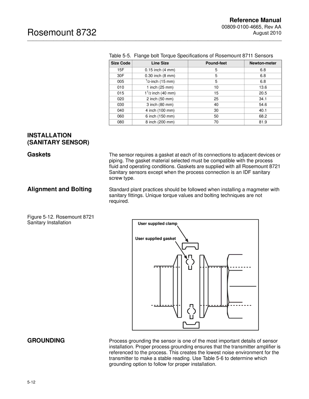
The sensor requires a gasket at each of its connections to adjacent devices or piping. The gasket material selected must be compatible with the process fluid and operating conditions. Gaskets are supplied with all Rosemount 8721 Sanitary sensors except when the process connection is an IDF sanitary screw type.
Standard plant practices should be followed when installing a magmeter with sanitary fittings. Unique torque values and bolting techniques are not required.
Figure 5-12. Rosemount 8721 Sanitary Installation
GROUNDING
User supplied clamp |
User supplied gasket |
Process grounding the sensor is one of the most important details of sensor installation. Proper process grounding ensures that the transmitter amplifier is referenced to the process. This creates the lowest noise environment for the transmitter to make a stable reading. Use Table
