Rosemount 8732
Reference Manual
KENT SENSORS
Kent Sensor to Rosemount 8732 Transmitter
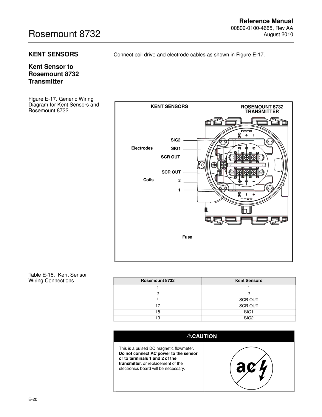
Connect coil drive and electrode cables as shown in Figure
Figure E-17. Generic Wiring Diagram for Kent Sensors and Rosemount 8732
Table E-18. Kent Sensor Wiring Connections
KENT SENSORS | ROSEMOUNT 8732 | |
|
| TRANSMITTER |
| SIG2 |
|
Electrodes | SIG1 |
|
| SCR OUT |
|
| SCR OUT |
|
Coils | 2 |
|
| 1 |
|
| Fuse |
|
Rosemount 8732 |
| Kent Sensors | ||||
1 |
|
| 1 | |||
2 |
|
| 2 | |||
|
|
|
|
|
| SCR OUT |
|
|
|
|
| ||
17 |
|
| SCR OUT | |||
18 |
|
| SIG1 | |||
19 |
|
| SIG2 | |||
|
|
|
|
|
|
|
|
|
|
|
|
|
|
This is a pulsed DC magnetic flowmeter.
Do not connect AC power to the sensor or to terminals 1 and 2 of the transmitter, or replacement of the electronics board will be necessary.