Rosemount 8732
Reference Manual
Troubleshooting the
8714i Meter Verification
Test
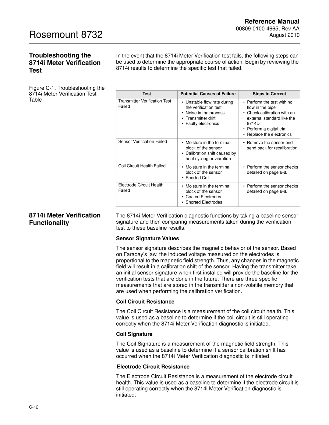
Figure C-1. Troubleshooting the
8714i Meter Verification Test
Table
8714i Meter Verification Functionality
In the event that the 8714i Meter Verification test fails, the following steps can be used to determine the appropriate course of action. Begin by reviewing the 8714i results to determine the specific test that failed.
Test | Potential Causes of Failure |
| Steps to Correct | |
Transmitter Verification Test | • | Unstable flow rate during | • | Perform the test with no |
Failed |
| the verification test |
| flow in the pipe |
| • | Noise in the process | • | Check calibration with an |
| • | Transmitter drift |
| external standard like the |
| • | Faulty electronics |
| 8714D |
|
|
| • | Perform a digital trim |
|
|
| • | Replace the electronics |
|
|
|
|
|
Sensor Verification Failed | • | Moisture in the terminal | • | Remove the sensor and |
|
| block of the sensor |
| send back for recalibration. |
| • | Calibration shift caused by |
|
|
|
| heat cycling or vibration |
|
|
|
|
|
|
|
Coil Circuit Health Failed | • | Moisture in the terminal | • | Perform the sensor checks |
|
| block of the sensor |
| detailed on page |
| • | Shorted Coil |
|
|
|
|
|
|
|
Electrode Circuit Health | • | Moisture in the terminal | • | Perform the sensor checks |
Failed |
| block of the sensor |
| detailed on page |
| • | Coated Electrodes |
|
|
| • | Shorted Electrodes |
|
|
|
|
|
|
|
The 8714i Meter Verification diagnostic functions by taking a baseline sensor signature and then comparing measurements taken during the verification test to these baseline results.
Sensor Signature Values
The sensor signature describes the magnetic behavior of the sensor. Based on Faraday’s law, the induced voltage measured on the electrodes is proportional to the magnetic field strength. Thus, any changes in the magnetic field will result in a calibration shift of the sensor. Having the transmitter take an initial sensor signature when first installed will provide the baseline for the verification tests that are done in the future. There are three specific measurements that are stored in the transmitter’s
Coil Circuit Resistance
The Coil Circuit Resistance is a measurement of the coil circuit health. This value is used as a baseline to determine if the coil circuit is still operating correctly when the 8714i Meter Verification diagnostic is initiated.
Coil Signature
The Coil Signature is a measurement of the magnetic field strength. This value is used as a baseline to determine if a sensor calibration shift has occurred when the 8714i Meter Verification diagnostic is initiated
Electrode Circuit Resistance
The Electrode Circuit Resistance is a measurement of the electrode circuit health. This value is used as a baseline to determine if the electrode circuit is still operating correctly when the 8714i Meter Verification diagnostic is initiated.