Rosemount 8732
Reference Manual
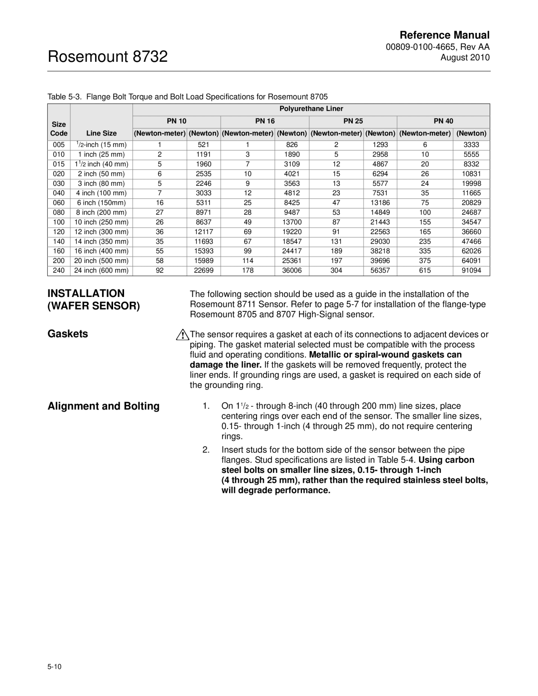
Table
|
|
|
|
|
| Polyurethane Liner |
|
|
|
|
| |
Size |
|
| PN 10 | PN 16 |
|
| PN 25 | PN 40 |
| |||
Code | Line Size | (Newton) | (Newton) | (Newton) |
| (Newton) | ||||||
005 | 1 |
| 521 | 1 | 826 | 2 |
| 1293 | 6 |
| 3333 | |
010 | 1 inch (25 mm) | 2 |
| 1191 | 3 | 1890 | 5 |
| 2958 | 10 |
| 5555 |
015 | 11/2 inch (40 mm) | 5 |
| 1960 | 7 | 3109 | 12 |
| 4867 | 20 |
| 8332 |
020 | 2 inch (50 mm) | 6 |
| 2535 | 10 | 4021 | 15 |
| 6294 | 26 |
| 10831 |
030 | 3 inch (80 mm) | 5 |
| 2246 | 9 | 3563 | 13 |
| 5577 | 24 |
| 19998 |
040 | 4 inch (100 mm) | 7 |
| 3033 | 12 | 4812 | 23 |
| 7531 | 35 |
| 11665 |
060 | 6 inch (150mm) | 16 |
| 5311 | 25 | 8425 | 47 |
| 13186 | 75 |
| 20829 |
080 | 8 inch (200 mm) | 27 |
| 8971 | 28 | 9487 | 53 |
| 14849 | 100 |
| 24687 |
100 | 10 inch (250 mm) | 26 |
| 8637 | 49 | 13700 | 87 |
| 21443 | 155 |
| 34547 |
120 | 12 inch (300 mm) | 36 |
| 12117 | 69 | 19220 | 91 |
| 22563 | 165 |
| 36660 |
140 | 14 inch (350 mm) | 35 |
| 11693 | 67 | 18547 | 131 |
| 29030 | 235 |
| 47466 |
160 | 16 inch (400 mm) | 55 |
| 15393 | 99 | 24417 | 189 |
| 38218 | 335 |
| 62026 |
200 | 20 inch (500 mm) | 58 |
| 15989 | 114 | 25361 | 197 |
| 39696 | 375 |
| 64091 |
240 | 24 inch (600 mm) | 92 |
| 22699 | 178 | 36006 | 304 |
| 56357 | 615 |
| 91094 |
INSTALLATION (WAFER SENSOR)
Gaskets
Alignment and Bolting
The following section should be used as a guide in the installation of the Rosemount 8711 Sensor. Refer to page
The sensor requires a gasket at each of its connections to adjacent devices or piping. The gasket material selected must be compatible with the process fluid and operating conditions. Metallic or
1.On 11/2 - through
2.Insert studs for the bottom side of the sensor between the pipe flanges. Stud specifications are listed in Table
(4 through 25 mm), rather than the required stainless steel bolts, will degrade performance.