Reference Manual
Rosemount 8732
Relief Valves
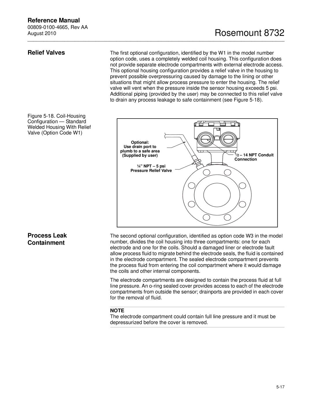
The first optional configuration, identified by the W1 in the model number option code, uses a completely welded coil housing. This configuration does not provide separate electrode compartments with external electrode access. This optional housing configuration provides a relief valve in the housing to prevent possible overpressuring caused by damage to the lining or other situations that might allow process pressure to enter the housing. The relief valve will vent when the pressure inside the sensor housing exceeds 5 psi. Additional piping (provided by the user) may be connected to this relief valve to drain any process leakage to safe containment (see Figure
Figure 5-18. Coil-Housing
Configuration — Standard
Welded Housing With Relief
Valve (Option Code W1)
Process Leak
Containment
Optional: |
|
Use drain port to |
|
plumb to a safe area | 1/2 – 14 NPT Conduit |
(Supplied by user) | |
| Connection |
¼'' NPT – 5 psi |
|
Pressure Relief Valve |
|
The second optional configuration, identified as option code W3 in the model number, divides the coil housing into three compartments: one for each electrode and one for the coils. Should a damaged liner or electrode fault allow process fluid to migrate behind the electrode seals, the fluid is contained in the electrode compartment. The sealed electrode compartment prevents the process fluid from entering the coil compartment where it would damage the coils and other internal components.
The electrode compartments are designed to contain the process fluid at full line pressure. An
NOTE
The electrode compartment could contain full line pressure and it must be depressurized before the cover is removed.