Rosemount 8732
Reference Manual
SENSOR CONNECTIONS
Rosemount Sensors
Transmitter to Sensor Wiring
This section covers the steps required to physically install the transmitter including wiring and calibration.
To connect the transmitter to a
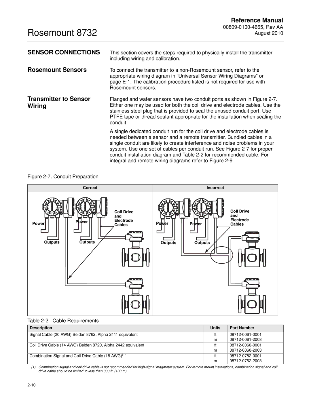
Flanged and wafer sensors have two conduit ports as shown in Figure
A single dedicated conduit run for the coil drive and electrode cables is needed between a sensor and a remote transmitter. Bundled cables in a single conduit are likely to create interference and noise problems in your system. Use one set of cables per conduit run. See Figure
Figure 2-7. Conduit Preparation
| Correct |
|
| Incorrect |
|
|
| Coil Drive |
|
| Coil Drive |
| Power | and |
|
| and |
Power | Electrode | Power | Power | Electrode | |
| Cables | Cables | |||
Outputs | Outputs |
| Outputs | Outputs |
|
Table 2-2. Cable Requirements
Description | Units | Part Number |
Signal Cable (20 AWG) Belden 8762, Alpha 2411 equivalent | ft | |
| m | |
Coil Drive Cable (14 AWG) Belden 8720, Alpha 2442 equivalent | ft | |
| m | |
Combination Signal and Coil Drive Cable (18 AWG)(1) | ft | |
| m |
(1)Combination signal and coil drive cable is not recommended for