Rosemount 8732
Reference Manual
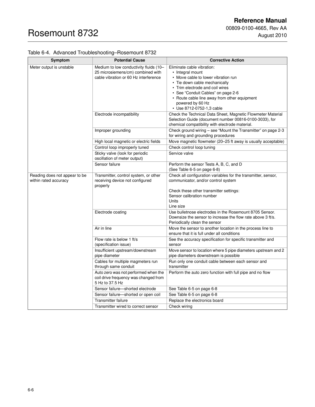
Table 6-4. Advanced Troubleshooting–Rosemount 8732
Symptom | Potential Cause |
| Corrective Action |
Meter output is unstable | Medium to low conductivity fluids (10– | Eliminate cable vibration: | |
| 25 microsiemens/cm) combined with | • | Integral mount |
| cable vibration or 60 Hz interference | • | Move cable to lower vibration run |
|
| • | Tie down cable mechanically |
|
| • | Trim electrode and coil wires |
|
| • See “Conduit Cables” on page | |
|
| • | Route cable line away from other equipment |
|
|
| powered by 60 Hz |
|
| • | Use |
| Electrode incompatibility | Check the Technical Data Sheet, Magnetic Flowmeter Material | |
|
| Selection Guide (document number | |
|
| chemical compatibility with electrode material. | |
| Improper grounding | Check ground wiring – see “Mount the Transmitter” on page | |
|
| for wiring and grounding procedures | |
| High local magnetic or electric fields | Move magnetic flowmeter | |
| Control loop improperly tuned | Check control loop tuning | |
| Sticky valve (look for periodic | Service valve | |
| oscillation of meter output) |
|
|
| Sensor failure | Perform the sensor Tests A, B, C, and D | |
|
| (See Table | |
Reading does not appear to be | Transmitter, control system, or other | Check all configuration variables for the transmitter, sensor, | |
within rated accuracy | receiving device not configured | communicator, and/or control system | |
| properly | Check these other transmitter settings: | |
|
| ||
|
| Sensor calibration number | |
|
| Units | |
|
| Line size | |
| Electrode coating | Use bulletnose electrodes in the Rosemount 8705 Sensor. | |
|
| Downsize the sensor to increase the flow rate above 3 ft/s. | |
|
| Periodically clean the sensor | |
| Air in line | Move the sensor to another location in the process line to | |
|
| ensure that it is full under all conditions | |
| Flow rate is below 1 ft/s | See the accuracy specification for specific transmitter and | |
| (specification issue) | sensor | |
| Insufficient upstream/downstream | Move sensor to location where 5 pipe diameters upstream and 2 | |
| pipe diameter | pipe diameters downstream is possible | |
| Cables for multiple magmeters run | Run only one conduit cable between each sensor and | |
| through same conduit | transmitter | |
| Auto zero was not performed when the | Perform the auto zero function with full pipe and no flow | |
| coil drive frequency was changed from |
|
|
| 5 Hz to 37.5 Hz |
|
|
| Sensor | See Table | |
| Sensor | See Table | |
| Transmitter failure | Replace the electronics board | |
| Transmitter wired to correct sensor | Check wiring | |