Reference Manual
Rosemount 8732
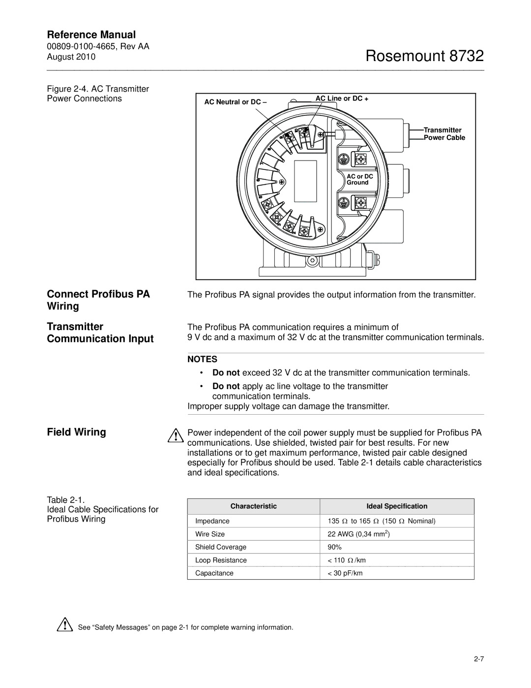
Figure 2-4. AC Transmitter Power Connections
Connect Profibus PA
Wiring
Transmitter
Communication Input
Field Wiring
Table
Ideal Cable Specifications for Profibus Wiring
AC Neutral or DC – | AC Line or DC + |
| |
| Transmitter |
| Power Cable |
| AC or DC |
| Ground |
The Profibus PA signal provides the output information from the transmitter.
The Profibus PA communication requires a minimum of
9 V dc and a maximum of 32 V dc at the transmitter communication terminals.
NOTES
•Do not exceed 32 V dc at the transmitter communication terminals.
•Do not apply ac line voltage to the transmitter communication terminals.
Improper supply voltage can damage the transmitter.
Power independent of the coil power supply must be supplied for Profibus PA communications. Use shielded, twisted pair for best results. For new installations or to get maximum performance, twisted pair cable designed especially for Profibus should be used. Table
Characteristic | Ideal Specification |
|
|
Impedance | 135 Ω to 165 Ω (150 Ω Nominal) |
Wire Size | 22 AWG (0,34 mm2) |
Shield Coverage | 90% |
Loop Resistance | < 110 Ω /km |
Capacitance | < 30 pF/km |
|
|
See “Safety Messages” on page