Chapter 12. Protective functions
12.3 Stall prevention
Group
Function group 1
I/O group
LED | Parameter Name | Set | |
Display | value | ||
|
| F59 |
|
| [Stall prevention select] |
| - |
|
|
|
|
|
|
| ||
|
|
|
|
|
|
|
|
| F60 |
|
| [Stall prevention level] |
| - |
|
|
|
|
|
|
| ||
|
|
|
|
|
|
|
|
| I54 |
| 7 |
| |||
|
| terminal select] |
| ||||
|
|
|
|
|
|
| |
|
|
|
|
|
|
|
|
| I55 |
| 7 |
| |||
|
| select] |
| ||||
|
|
|
|
|
|
| |
Min/Max setting
0/7
30/150
0/17
| Factory |
| Unit |
|
| default |
|
| |
|
|
|
| |
|
|
|
|
|
3 |
|
|
| |
150%
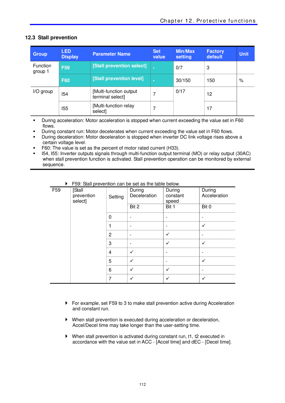
During acceleration: Motor acceleration is stopped when current exceeding the value set in F60 flows.
During constant run: Motor decelerates when current exceeding the value set in F60 flows.
During deceleration: Motor deceleration is stopped when inverter DC link voltage rises above a certain voltage level.
F60: The value is set as the percent of motor rated current (H33).
I54, I55: Inverter outputs signals through
F59: Stall prevention can be set as the table below.
F59 | [Stall |
| During | During | During |
| prevention | Setting | Deceleration | constant | Acceleration |
| select] |
|
| speed |
|
|
|
| Bit 2 | Bit 1 | Bit 0 |
|
|
|
|
|
|
|
| 0 | - | - | - |
|
|
|
|
|
|
|
| 1 | - | - | 9 |
|
|
|
|
|
|
|
| 2 | - | 9 | - |
|
|
|
|
|
|
|
| 3 | - | 9 | 9 |
|
|
|
|
|
|
|
| 4 | 9 | - | - |
|
|
|
|
|
|
|
| 5 | 9 | - | 9 |
|
|
|
|
|
|
|
| 6 | 9 | 9 | - |
|
|
|
|
|
|
|
| 7 | 9 | 9 | 9 |
|
|
|
|
|
|
For example, set F59 to 3 to make stall prevention active during Acceleration and constant run.
When stall prevention is executed during acceleration or deceleration,
Accel/Decel time may take longer than the
When stall prevention is activated during constant run, t1, t2 executed in accordance with the value set in ACC - [Accel time] and dEC - [Decel time].
112
