ENGLISH
E.Blower Belt
1.Remove the six screws shown in Figure
2.Check the blower belt for the proper 1/4" (6.4mm) deflection at the center, and for cracking or excessive wear. See Figure
3.If necessary, adjust the tension of the belt by loosening the four motor mounting bolts. Reposition the motor as neccessary until the correct 1/4" (6.4mm) deflection is reached, then tighten the bolts.
F.Lubricating the Blower Fan Bearings
1.Use a grease gun to lubricate the main blower fan shaft bearings, as shown in Figure
When lubricating the bearings:
•Use a
•Add the grease slowly until a small bead of grease is present at the seals. AVOID OVERGREASING. Excessive greasing may cause harm to the bearing.
2.Manually turn the blower shaft by pulling on the belt to purge the grease. Wipe off any excess grease.
3.Replace the rear panel onto the oven.
IV. MAINTENANCE - EVERY 6 MONTHS
A.Check that the oven is cool and the power is disconnected, as described in the warning at the beginning of this Section.
B.Check for excessive wear on the conveyor drive motor brushes. The brushes should be replaced if they have worn to less than 1/4" (6.4mm) in length. Be sure to replace the brushes in exactly the same position.
C.For gas ovens, inspect and clean the burner nozzle and the spark electrode assembly.
D.Check the conveyor drive shaft bushings and spacers. Replace the components if they are worn.
Figure 4-6 - Rear panel access
Remove six (6)
screws to remove
rear panel
Bearings (2 total)
Grease fitting
(1 per
bearing)
Blower belt
Blower motor
Loosen four (4) screws to adjust motor position and belt tension
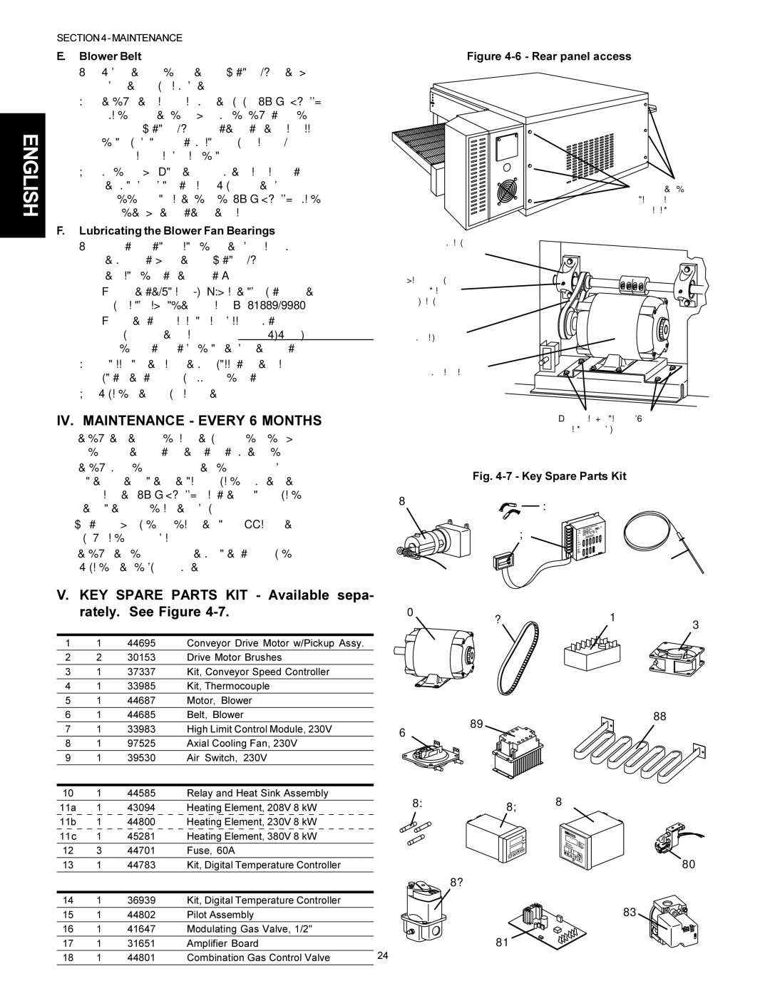
Fig. 4-7 - Key Spare Parts Kit
1 | 2 |
|
3
4
V. KEY SPARE PARTS KIT - Available sepa- rately. See Figure 4-7.
Item | Qty. | Part No. | Description |
1 | 1 | 44695 | Conveyor Drive Motor w/Pickup Assy. |
2 | 2 | 30153 | Drive Motor Brushes |
3 | 1 | 37337 | Kit, Conveyor Speed Controller |
4 | 1 | 33985 | Kit, Thermocouple |
5 | 1 | 44687 | Motor, Blower |
5 | 6 | 7 |
|
| 8 | ||
|
|
|
6 | 1 | 44685 | Belt, Blower |
7 | 1 | 33983 | High Limit Control Module, 230V |
8 | 1 | 97525 | Axial Cooling Fan, 230V |
9 | 1 | 39530 | Air Switch, 230V |
ELECTRIC OVENS ONLY: |
| ||
10 | 1 | 44585 | Relay and Heat Sink Assembly |
9
10
11
11a | 1 | 43094 |
|
|
|
|
| Heating Element, 208V 8 kW |
| ||||||||||||||||||||||||||
|
|
|
|
|
|
|
|
|
|
|
|
|
|
|
|
|
|
|
|
|
|
|
|
|
|
|
|
|
|
|
|
|
|
|
|
11b | 1 | 44800 |
|
|
|
|
| Heating Element, 230V 8 kW |
| ||||||||||||||||||||||||||
11c | 1 | 45281 |
|
|
|
|
| Heating Element, 380V 8 kW |
| ||||||||||||||||||||||||||
12 | 3 | 44701 |
|
|
|
|
| Fuse, 60A |
| ||||||||||||||||||||||||||
13 | 1 | 44783 |
|
|
|
|
| Kit, Digital Temperature Controller |
| ||||||||||||||||||||||||||
GAS OVENS ONLY: |
|
|
|
|
|
|
|
|
|
|
|
|
|
|
|
|
|
|
|
|
|
|
|
| |||||||||||
14 | 1 | 36939 |
|
|
|
|
| Kit, Digital Temperature Controller |
| ||||||||||||||||||||||||||
15 | 1 | 44802 |
|
|
|
|
| Pilot Assembly |
| ||||||||||||||||||||||||||
16 | 1 | 41647 |
|
|
|
|
| Modulating Gas Valve, 1/2" |
| ||||||||||||||||||||||||||
17 | 1 | 31651 |
|
|
|
|
| Amplifier Board |
| ||||||||||||||||||||||||||
18 | 1 | 44801 |
|
|
|
|
| Combination Gas Control Valve | 24 | ||||||||||||||||||||||||||
12 | 13 | 14 |
|
|
15
16
18
17