CPCI-6020 CompactPCI Single Board Computer
Contact Address
Contents
Contents
Controls, LEDs, and Connectors
Contents
Firmware
Cnfg and ENV Commands
Contents
List of Tables
List of Tables
List of Figures
List of Figures
About this Manual
Overview of Contents
Abbreviation Description
Abbreviations
About this Manual
Bold
Conventions
About this Manual Abbreviation Description
Notation Description
Part Number Publication Date Description
Summary of Changes
About this Manual Notation Description
Reader-comments@ecc.mot.com
Comments and Suggestions
About this Manual
EMC
Safety Notes
Safety Notes
Operation
Installation
Safety Notes
Environment
Rear Transition Module
Safety Notes
EMV
Sicherheitshinweise
Sicherheitshinweise
Betrieb
Installation
Umweltschutz
Sicherheitshinweise
Introduction
Features
Features
Feature Description
CPCI-6020 5E Only
Standard Compliances
Board Standard Compliances
IntroductionStandard Compliances
Model Number Description
Ordering Information
Supported Board Models
Ordering InformationIntroduction
Introduction
Board Accessories
Unpacking and Inspecting the Board
Hardware Preparation and Installation
Overview
Startup Overview
Overview of Start-up Procedure
Hardware Preparation and Installation
Environmental Requirements
Environmental and Power Requirements
Equipment RequiredHardware Preparation and Installation
Equipment Required
Core
Specifications
Characteristics Operating Nonoperating
Thermal Requirements
Hardware Configuration
Power Requirements
Baseboard and RTM Power Requirements
CPCI-6020 Baseboard Preparation
Flash Bank Selection
Jumper Settings
Jumper Settings
Enable/Disable +12 V and -12 V Use
Harrier Power Up Configuration Header
PMC 66 MHz Disable
Pin # Signal
Hardware Installation
Enable Write-Protect for Entire Flash on Bank a
Remote Switch
Procedure
PMC Module Installation
PMC Module Installation
CompactFlash Memory Card Installation
Before You Install or Remove a Board
Before You Install or Remove a Board
Understanding Hot Swap
Watch for Bent Pins or Other Damage
Use Caution When Installing or Removing Boards
Recognize Different Injector/Ejector Lever Types
Recognize Different Injector/Ejector Lever Types
Card Rail Color Glyph Usage
Slot Usage Indicators
Verify Slot Usage
Preserve EMI Compliance
Installing and Removing a Module
Installing and Removing a Module
Installing and Removing a Module
Removal Procedure
Startup and Operation
Power-up Procedure
System Considerations
System Considerations
System Considerations
CPCI-6020 Baseboard Layout
Controls, LEDs, and Connectors
Pin Signal
Front Panel Connectors and LEDs
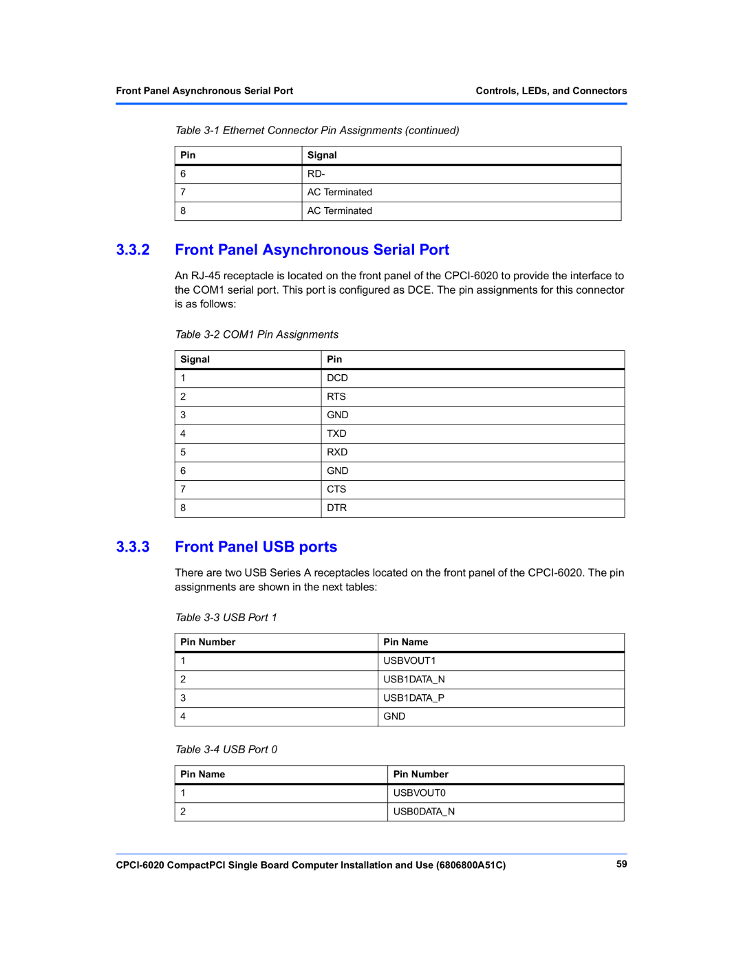
Ethernet Connector Pin Assignments
Controls, LEDs, and Connectors
USB Port
Front Panel Asynchronous Serial Port
Front Panel USB ports
COM1 Pin Assignments
CompactPCI Bus Connectors
Connector Pin Assignments
ABORT# Switch
RESET# Switch
Pin Row a Row B Row C Row D Row E
J1 CompactPCI Connector
J2 CompactPCI Connector
CompactPCI Bus Connectors
Controls, LEDs, and ConnectorsCompactPCI Bus Connectors
CompactPCI User I/O Connector
CompactPCI User I/O Connector
J3 CompactPCI User I/O Connector
Signal Descriptions for the J3 Connector
10 J4 Local PCI Expansion Connector Pinout
Signal Description
11 J5 User I/O Connector
12 J5 Signal Descriptions
Spkrocl
Controls, LEDs, and ConnectorsCompactPCI User I/O Connector
Resetl
Intrq
Pin Pin Name
Memory Mezzanine Connectors
13 J8 and J27 Memory Mezzanine Connector
Memory Mezzanine ConnectorsControls, LEDs, and Connectors
14 PMC Connector J11 Pin Assignments
PCI Mezzanine Card PMC Connectors
RST# Motrsvd
15 J12 PMC Connector J12 Pin Assignments
FRAME# GND IRDY# DEVSEL# LOCK# SDONE# SBO# PAR VIO
TRST# TMS TDO TDI GND Pcirsvd Motrsvd
16 PMC Connector J13 Pin Assignments
GND GND a
17 PMC Connector J14 Pin Assignments
WPL GND
Lock Down Flash Enable Jumper
18 J17 Lock Down Flash Enable Jumper
Controls, LEDs, and ConnectorsLock Down Flash Enable Jumper
Flash Write Protect Enable Jumper
PMC 66 Mhz Disable Jumper
Remote Switch Connector
23 J24 Xport Flash Bank Select Header
Harrier Power Up Configuration
Xport Flash Bank Select Header
RISCWatch Header
Mictor Debug ConnectorControls, LEDs, and Connectors
Mictor Debug Connector
25 J28 Debug Connector
PD0 PD1 PD2 PD3 PD4 PD5 PD6 PD7 PD8 PD9
Controls, LEDs, and ConnectorsMictor Debug Connector
PDPAR6 PDPAR7
PDPAR0 PDPAR1
PDPAR2 PDPAR3
PDPAR4 PDPAR5
TT3
TT0 TSIZ0
TT1 TSIZ1
TT2 TSIZ2
CPUREQ1L INT0L
Hresetl Naprun
SRESET0DL Qackl
Hresetl Cputdo
Mictor Debug Connector
Functional Description
Functional Description
Block Diagram
Local PCI Bus Resources
Local PCI Bus Resources
PCI Bus a Resources
ISA Bridge, Including Eide Function
PCI Bus B Resources
PCI Bus B Resources
PMC Slot
Secondary Ethernet Channel
Special Function Processor PMC Pins
PrPMC Signal Pin Number Support
2 L2 Cache
Processor Bus Resources
Harrier System Memory Controller and PCI Host Bridge Asic
Processor
Dual Harrier Assignments
Harrier Power-Up Configuration
Harrier Power-Up Configuration Settings
Harrier Power-Up ConfigurationFunctional Description
Harrier a Memory Bus
Debug Connector
ECC Memory Bus Resources
PPC Bus Arbitration
Expansion Sdram Memory Mezzanine Size Options
Harrier Xport Resources
Harrier B Memory Bus
3 RAM500 Memory Mezzanine
Harrier A, Channel
Harrier A, Channel 0 Onboard Bank a Flash
Harrier A, Channel 1 Socketed Bank B Flash
Harrier A, Channel 2 NVRAM, RTC, External Register Set
1 I2C Bus Resources Serial Eeprom
3 32-Bit Timers
Watchdog Timers
Other Harrier Resources
PPC to PCI Clock Ratios
Other Board Resources
Miscellaneous Control and Status
Clock Generator
Onboard Power Supplies
Onboard Power Supplies
Board Reset Logic
Devices Bus
Reset Sources and Devices Affected
Local Processo Harrier
CompactPCI Device Affected
Front Panel Resources
Soft Reset
ABORT# and RESET# Switches
HSC Bridge Board Interface
Hot Swap Support
High Availability Support
On-Board LEDs
System Slot Hot Swap
Local CompactPCI Bus Interface
Secondary Bus Arbitration
Secondary Bus Tri-Stating
Functional Description Eide Interface
Eide Interface
Ethernet Interface
PMC Interface Module PIM
Asynchronous Serial Ports
19 I/O Signal Multiplexing Iomux
Asynchronous Serial Ports
Synchronous Serial Ports
RI4
Multiplexing Sequence of the Iomx Function
Mxdo From CPCI-6020 Mxdi From CPCI-6020-MCPTM-01
TM4
Serial Interface Modules SIM
Serial Interface Modules SIM
104
PMC Interface Module Form Factor
Floppy Disk Port
PMC Interface Connector
Host I/O Connector
Speaker Port
106
PPCBug Basics
Firmware
PPCBug Overview
Firmware
Memory Requirements
PPCBug Implementation
MPU, Hardware and Firmware Initialization
MPU, Hardware and Firmware Initialization
110
Using PPCBug
Debugger Commands
Firmware Using PPCBug
Command Description
Debugger Commands
Debugger Commands
112
FirmwareDebugger Commands
Debugger CommandsFirmware
114
Diagnostic Tests
FirmwareDiagnostic Tests
Command Description Write Loop
Test Set Description
Diagnostic Test Groups
Diagnostic Tests
116
RAM500 Description
RAM500 Memory Expansion Module
118
RAM500 Module Installation
RAM500 Sdram Memory Size Options
RAM500 Memory Expansion Module
Srom
RAM500 Feature Summary
Features
Host Clock Logic
RAM500 Connectors
Bottom Side Memory Expansion Connector P1
RAM500 Bottom Side Connector P1 Pin Assignments
DQ08 DQ09 DQ10 DQ11 DQ12 DQ13 DQ14 DQ15
122
CKD00 CKD01 CKD02 CKD03 CKD04 CKD05
CKD06 CKD07 BA1 BA0
Top Side Memory Expansion Connector J1
Top Side Memory Expansion Connector J1
RAM500 Top Side Connector J1 Pin Assignments
A1SPD MEZZ2L
CSE0L
DQMB1
SDA
SDRAMCLK4
RAM500 Programming Issues
RAM500 Programming IssuesRAM500 Memory Expansion Module
GND SDRAMCLK3
126
General Description
Transition Module Preparation and Installation
128
Transition Module Preparation and Installation
Component Layout
Component Layout
130
Rear Panel Connectors
Unpacking and Inspecting the RTM
Unpacking and Inspecting the RTM
Preparing the Transition Module
Serial Ports 1
Model Number
Serial Ports 3
SIM Model Numbers
Interface
Serial Interface Module Circuitry
Serial Interface Module Circuitry
134
Port Configuration
Port Configuration
136
Installing the SIMs
Installing the SIMs
138
Installing the PIM
Installing the PIM
140
Installing and Removing the Transition Module
Type Number Description
Connectors and Cables
Rear Transition Module Connectors/Headers
Connectors and Cables
MCPTM-01
Rear Transition Module Cables
PLD Jtag
Part Number Description
Connector Pin Assignments
CompactPCI Connectors
PMC I/O Module Connector
PMC I/O Module Host I/O Connector Pin Assignments
144
PMC I/O Module PMC I/O Connector Pin Assignments
IN2RI
Outrts Outrxd Outtxd I2CCLK I2CDAT
PMC I/O Module PMC I/O Connector Pin Assignments
COM1 Connector Pin Assignments
3 10BaseT/100BaseTx Connectors
4 COM1 Connector
10BaseT/100BaseTx Connector Pin Assignments
Eide Header Pin Assignments
5 COM2 Header
Eide Header
COM2 Header Pin Assignments
10 Floppy Header Pin Assignments
8 +5VDC Power Connector
11 +5Vdc Power Connector
Floppy Port Header
Keyboard/Mouse Connector
Keyboard/Mouse Connector
12 Keyboard/Mouse Connector Pin Assignments
13 Sync/Async Serial Connector Pin Assignments
150
14 Speaker Output Connector Pin Assignments
Speaker Output Header
Detail Value
Cnfg and ENV Commands
Cnfg Configure Board Information
152
Configuring the PPCBug Parameters
Cnfg and ENV Commands
ENV Set Environment
Probe System for Supported I/O Controllers Y/N = Y?
Configuring the PPCBug Parameters
154
Nvram Bootlist GEV.fw-boot-path Boot Enable Y/N = N?
ROM Boot Enable Y/N = N?
156
Watchdog shutdown at board reset Y/N = N?
158
Memory Size Enable Y/N = Y?
Serial Startup Code Master Enable Y/N = N?
160
Table A-1 Embedded Communications Computing Documents
Related Documentation
Embedded Communications Computing Documents
Manufacturers’ Documents
Table A-3 Related Specifications
Related Specifications
MPR-PPC-RPU-02
Related SpecificationsRelated Documentation
Number or Search
Document Title and Source Term
164
Related Documentation
Index
Symbols
166
167
168