Appendix C: MVP428 Upgrade Card
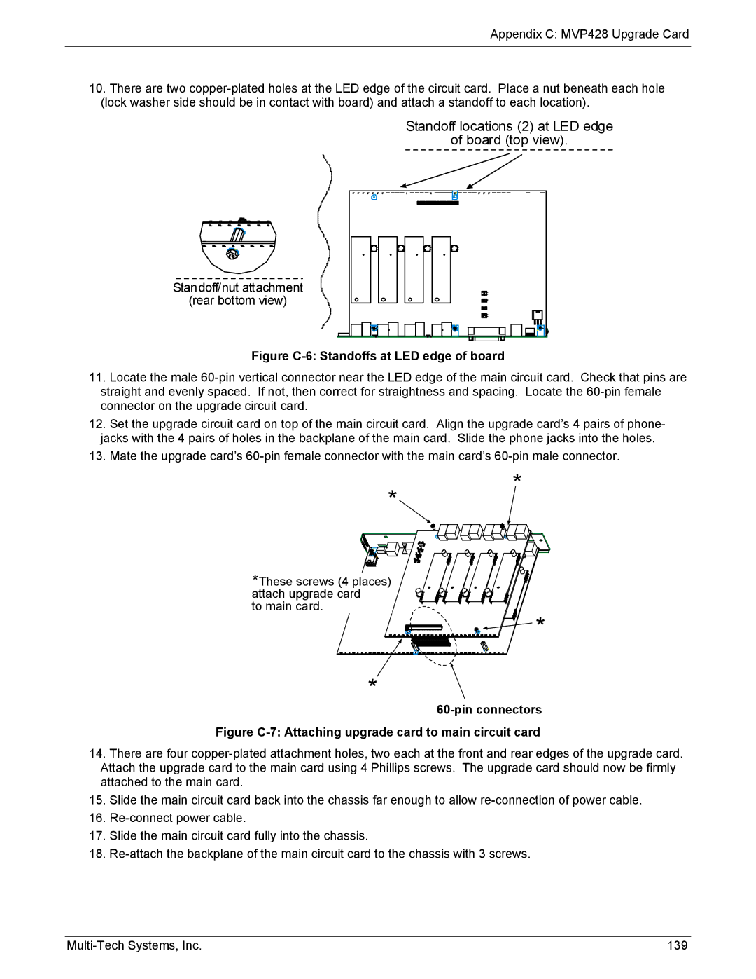
10.There are two
Standoff locations (2) at LED edge
of board (top view).
Standoff/nut attachment
(rear bottom view)
Figure C-6: Standoffs at LED edge of board
11.Locate the male
12.Set the upgrade circuit card on top of the main circuit card. Align the upgrade card’s 4 pairs of phone- jacks with the 4 pairs of holes in the backplane of the main card. Slide the phone jacks into the holes.
13.Mate the upgrade card’s
* *
*These screws (4 places) attach upgrade card
to main card.
* |
*
60-pin connectors
Figure C-7: Attaching upgrade card to main circuit card
14.There are four
15.Slide the main circuit card back into the chassis far enough to allow
16.
17.Slide the main circuit card fully into the chassis.
18.
139 |
