|
|
| Chapter 4: Configuring your VOIP | |
|
|
|
|
|
|
|
|
|
|
|
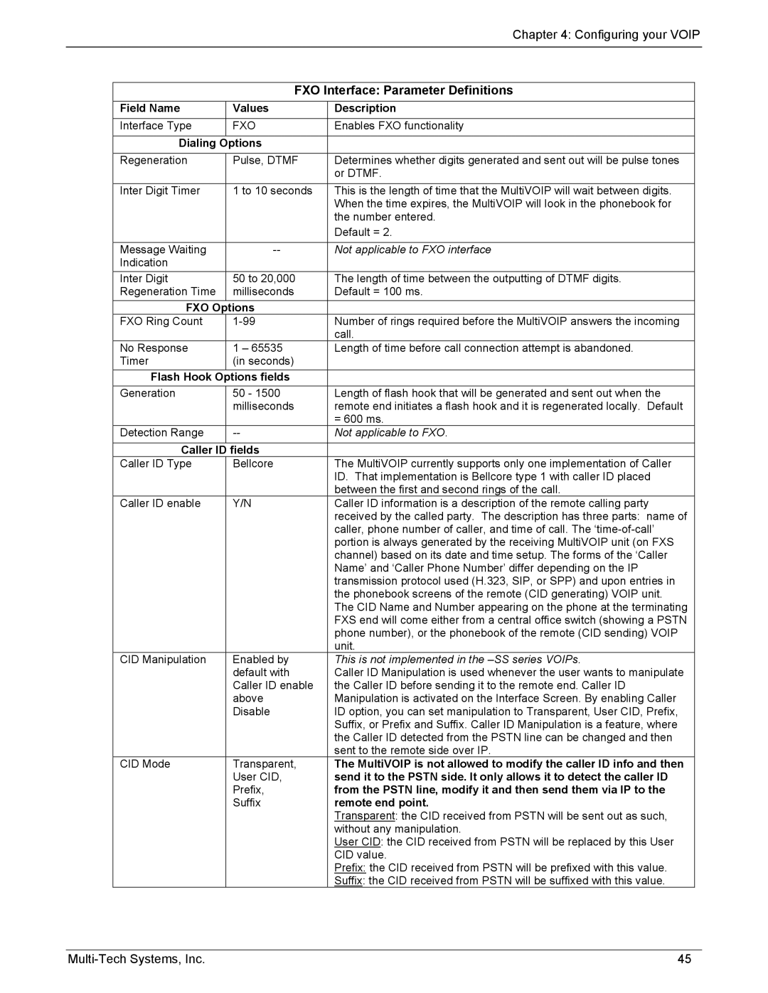
| FXO Interface: Parameter Definitions | ||
| Field Name | Values | Description |
|
| Interface Type | FXO | Enables FXO functionality |
|
|
|
|
|
|
| Dialing | Options |
|
|
|
|
|
|
|
| Regeneration | Pulse, DTMF | Determines whether digits generated and sent out will be pulse tones | |
|
|
| or DTMF. |
|
|
|
|
|
|
| Inter Digit Timer | 1 to 10 seconds | This is the length of time that the MultiVOIP will wait between digits. | |
|
|
| When the time expires, the MultiVOIP will look in the phonebook for |
|
|
|
| the number entered. |
|
|
|
| Default = 2. |
|
|
|
|
|
|
| Message Waiting | Not applicable to FXO interface | ||
| Indication |
|
|
|
| Inter Digit | 50 to 20,000 | The length of time between the outputting of DTMF digits. |
|
| Regeneration Time | milliseconds | Default = 100 ms. |
|
| FXO Options |
|
| |
| FXO Ring Count | Number of rings required before the MultiVOIP answers the incoming |
| |
|
|
| call. |
|
| No Response | 1 – 65535 | Length of time before call connection attempt is abandoned. |
|
| Timer | (in seconds) |
|
|
| Flash Hook Options fields |
|
| |
| Generation | 50 - 1500 | Length of flash hook that will be generated and sent out when the |
|
|
| milliseconds | remote end initiates a flash hook and it is regenerated locally. Default |
|
|
|
| = 600 ms. |
|
| Detection Range | Not applicable to FXO. |
| |
|
|
|
|
|
| Caller ID | fields |
|
|
| Caller ID Type | Bellcore | The MultiVOIP currently supports only one implementation of Caller |
|
|
|
| ID. That implementation is Bellcore type 1 with caller ID placed |
|
|
|
| between the first and second rings of the call. |
|
| Caller ID enable | Y/N | Caller ID information is a description of the remote calling party |
|
|
|
| received by the called party. The description has three parts: name of |
|
|
|
| caller, phone number of caller, and time of call. The |
|
|
|
| portion is always generated by the receiving MultiVOIP unit (on FXS |
|
|
|
| channel) based on its date and time setup. The forms of the ‘Caller |
|
|
|
| Name’ and ‘Caller Phone Number’ differ depending on the IP |
|
|
|
| transmission protocol used (H.323, SIP, or SPP) and upon entries in |
|
|
|
| the phonebook screens of the remote (CID generating) VOIP unit. |
|
|
|
| The CID Name and Number appearing on the phone at the terminating |
|
|
|
| FXS end will come either from a central office switch (showing a PSTN |
|
|
|
| phone number), or the phonebook of the remote (CID sending) VOIP |
|
|
|
| unit. |
|
| CID Manipulation | Enabled by | This is not implemented in the |
|
|
| default with | Caller ID Manipulation is used whenever the user wants to manipulate |
|
|
| Caller ID enable | the Caller ID before sending it to the remote end. Caller ID |
|
|
| above | Manipulation is activated on the Interface Screen. By enabling Caller |
|
|
| Disable | ID option, you can set manipulation to Transparent, User CID, Prefix, |
|
|
|
| Suffix, or Prefix and Suffix. Caller ID Manipulation is a feature, where |
|
|
|
| the Caller ID detected from the PSTN line can be changed and then |
|
|
|
| sent to the remote side over IP. |
|
| CID Mode | Transparent, | The MultiVOIP is not allowed to modify the caller ID info and then |
|
|
| User CID, | send it to the PSTN side. It only allows it to detect the caller ID |
|
|
| Prefix, | from the PSTN line, modify it and then send them via IP to the |
|
|
| Suffix | remote end point. |
|
|
|
| Transparent: the CID received from PSTN will be sent out as such, |
|
|
|
| without any manipulation. |
|
|
|
| User CID: the CID received from PSTN will be replaced by this User |
|
|
|
| CID value. |
|
|
|
| Prefix: the CID received from PSTN will be prefixed with this value. |
|
|
|
| Suffix: the CID received from PSTN will be suffixed with this value. |
|
45 |