Model Nos. WJ-SX650 Series
English Version
Important Safety Instructions
Contents
Trademarks and Registered Trademarks
Disclaimer of Warranty
Limitation of Liability
Precautions
Preparations pages xx, xx, xx
About These Operating Instructions
Alarm operation and alarm event can be scheduled
Features
Authentication by user IDs, passwords, and level settings
Timer event and camera event can be scheduled
Front View
WJ-SX650 Matrix Switcher/WJ-SX650U Card Cage
Rear View
1Signal Ground Terminal Signal GND
IN-3 board
Video Input Board WJ-PB65C32
A-3/IN B-3/IN C-3 board
X-2 board
OUT X-1 board
Video Output Board WJ-PB65M16
OUT X-3 board
OUT X-2 board
Monitor Display Information
WV-CU950/650
System Controller Display Information
Camera/recorder/sequence number 001 to 999 Camera number
WV-CU360C/CJ
Checking Board Composition
Installations
Switch Settings for Video Input Main Board
Host Func
Switch Settings for Video Output Main Board
Front view of video output main board
Mounting Video Input and Output Boards
Board Mounting Procedure
EIA equivalents Products of other manufacturers EIA
Installing the Main Unit
Places to avoid
Rack Mounting
Standards
Connections
Recommended
This unit x 1, camera x 30, monitor x 16, and recorder x
Basic System Connections
This unit x 3, camera x 150, monitor x 32, and recorder x
Expanded System Connections
This unit x 4, camera x 240, monitor x 32, and recorder x
Line termination OFF
Card Cage Connections
OFF
Camera Connections
RS-485 Camera Connections
WV-CA48/JN
Connection
Daisy Chain Connection
PC Connection
Monitor Connections
Recorders unit address Camera in channel Video input board
Connection to Video Output Connectors of Recorders
Recorder Connection
Recorder number Unit Address System
Video OUT
Connection between Recorders and Video Input Boards
OFF
System Controller Connection
Recorder Settings
Terminal Mode Connection
Example
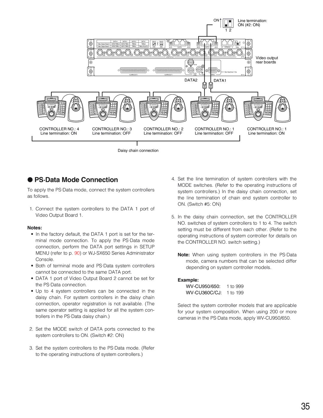
PS·Data Mode Connection
GND
Alarm Sensor Connections
External Device Connections
Pin No Designation
Monitor
System Status Check
Terminal Duration Remarks
Display example of System Status
Data 1, 2, 5 and 6 ports Tmnl Data 3, 4, 7 and 8 ports HDR
Setup Procedure
Setup Menu
Recorder 1 to 10 on Recorder 11 to 16 OFF
Setup Menu
Uninstallation
WJ-SX650 Series Administrator Console
Installation and Uninstallation
Installation
Tool Bar
User Name admin Password sx650
Starting Up
Window Details
Reference No Explanation
Tooltip Details
2005 to 2099 Year
ON, OFF, AUTO, B/W setting
Sequence
System
Display
Camera
Operator
Alarm
Schedule
Communication
Controller
Top Menu
Setup Menu OSD
Basic Operations
Day Time
Alarm Menu
Year
Month
Recorder Alarm
Terminal Alarm Menu
Input Board
Data bit 8 bits Parity check None Stop bit 1 bit
System Menu
Data Port Menu
800 bps/9 600 bps/19 200 bps/38 400 bps
RS485
VD2/DATA/CABLE Compensation Menu
RS485 Camera Menu
VD2
Information
Operator Registration
Login and Logout
Operation End Logout
Power-on/off
Operation Start Login
Operation Start/End Auto Login/Logout
Monitor Lock
Monitor Control
Monitor Selection
Camera Selection Recall
Preset Position Control
Camera Control
Camera Selection
Available buttons and functions F1 All home positions
All Cameras Control
Recorder Control
Recorder Selection
Recorder Control End
Tour Sequence
Group Preset
Running Sequence
Descriptions of Sequence
Setting item Parameter Remarks
Sequence Setting
Tour Sequence
Group Sequence/Preset
Sequence step forward/backward
Sequence Pause
Sequence Stop
Available operations during sequence pause
Terminal alarm setting
Alarm Descriptions
Alarm Occurrence
Spot
Alarm Modes
Group Sequence/Preset
Video Loss
Alarm Control
Details on Alarm History Display
Return to Alarm Mode Status
Alarm Suspension
Alarm History Display
REC
Auto Track
Timer Descriptions
Timer Event
Camera Event
Scene Patrols
Alarm in Camera Not Use
Cleaning
BW and Scene Patrols
Operation list of WV-CU950/650 and WV-CU360C/CJ
Terminal Mode Operation
Alarm recover WV-CU950/650
Lists of Operations and Functions
CU360C/CJ
Function list of WV-CU950/650 and WV-CU360C/CJ
Function WV-CU950/650
WV-CU950/650, WV
Event
Shift + Setup
ALL
CAM ID
ACK
ALM Reset
Shift + ALM ALL Reset Shift + ALL Reset
ALM Recall
Camera control
Near
Focus FAR
Focus Near
Focus FAR + Focus
Wiper
Shift + CAM Func
Recorder control
DEF on Shift + DEF on OFF DEF OFF Shift + DEF OFF
Screen SEL
OSD
OSD ON/OFF
→ Multi Screen
Stop
Play
Pause
GO to Last
Recorder +
If you select a recorder, and then press the Search button
Menu Flow WV-CU950/650
If you press the Menu button without selecting a recorder
If you select a recorder, and then press the Menu button
PS·Data Mode Operations
Operation Other than Terminal Mode
Connections and Operations
Controlling from a Web Browser Accessing a Recorder
Controlling from a PC
Monitor lock Refer to p
Camera Access Refer to p Recorder Access Refer to p
Alarm event Refer to p
Glossary
Page
Matrix Switcher WJ-SX650 Series
Troubleshooting
RS-485 communication
Coaxial communication
Problem Check item and remedy
Check if the alarm event has been set
WJ-SX650 Series Administrator Console
Problem Check item and remedy Reference
Power Cord, Connectors, and Power Plug
Matrix Switcher WJ-SX650 Series
Specifications
Video Output Board WJ-PB65M16
Card Cage WJ-SX650U
Video Input Board WJ-PB65C21
CD-ROM
Standard Accessories
Expansion Cable Kit WJ-CA65L20K/WJ-CA65L07K
Sub/BNC Video Cable WJ-CA68
N0805-0 V8QA6300AN