■Camera Connections
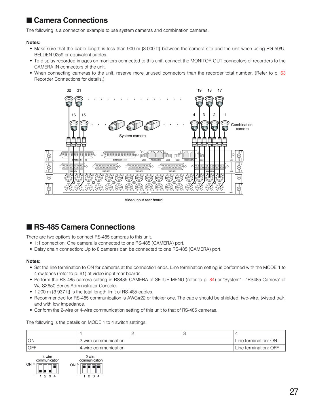
The following is a connection example to use system cameras and combination cameras.
Notes:
•Make sure that the cable length is less than 900 m {3 000 ft} between the camera site and the unit when using
•To display recorded images on monitors connected to this unit, connect the MONITOR OUT connectors of recorders to the CAMERA IN connectors of the unit.
•When connecting cameras to the unit, reserve more unused connectors than the recorder total number. (Refer to p. 63 Recorder Connections for details.)
32 | 31 |
|
|
|
|
|
|
|
|
|
|
|
|
| 19 | 18 | 17 |
| 16 | 15 |
|
|
|
|
|
|
|
|
|
|
| 4 | 3 | 2 | 1 |
|
|
|
|
|
|
|
|
|
|
|
|
|
|
|
|
| Combination |
|
|
|
|
|
|
|
|
|
|
|
|
|
|
|
|
| camera |
|
|
|
|
|
| System camera |
|
|
|
|
|
|
|
|
| ||
|
|
|
|
|
|
|
| 4 |
| 3 |
| 2 |
|
| 1 |
|
|
| EXTENSION | 3 IN |
|
| EXTENSION 2 IN |
| MODE | RS485 (CAMERA) |
| MODE | MODE |
| RS485 (CAMERA) | MODE |
| IN | |
VIDEO OUT 4 |
|
| VIDEO OUT 3 |
|
|
| VIDEO OUT 2 |
|
| VIDEO OUT 1 |
|
|
| ALARM IN | IN | ||
| 32 | 31 | 30 | 29 | 28 | 27 | 26 | 25 | 24 | 23 |
| 22 | 21 | 20 | 19 | 18 | 17 |
| 16 | 15 | 14 | 13 | 12 | 11 | 10 | 9 | 8 | 7 |
| 6 | 5 | 4 | 3 | 2 | 1 |
|
|
|
|
|
|
|
| CAMERA IN |
|
|
|
|
|
|
|
| IN |
Video input rear board
■RS-485 Camera Connections
There are two options to connect
•1:1 connection: One camera is connected to one
•Daisy chain connection: Up to 8 cameras can be connected to one
Notes:
•Set the line termination to ON for cameras at the connection ends. Line termination setting is performed with the MODE 1 to 4 switches (refer to p. 61) at video input rear boards.
•Perform the
•1 200 m {3 937 ft} is the total length limit of
•Recommended for
•Conform the
The following is the details on MODE 1 to 4 switch settings.
|
|
|
|
|
|
|
|
|
|
|
|
|
|
|
|
| 1 |
|
|
|
|
|
|
|
|
| 2 | 3 | 4 | |||||
|
|
|
|
|
|
|
|
|
|
|
|
|
|
|
|
|
| |||||||||||||||||
ON |
|
|
|
|
|
|
|
|
|
|
|
|
|
| Line termination: ON | |||||||||||||||||||
|
|
|
|
|
|
|
|
|
|
|
|
|
|
|
|
| ||||||||||||||||||
OFF |
|
|
|
|
|
|
|
|
|
|
|
|
|
| Line termination: OFF | |||||||||||||||||||
|
|
|
|
|
|
|
|
|
|
|
|
|
|
|
|
|
|
|
|
|
|
|
|
|
|
|
|
|
|
|
|
| ||
|
|
|
|
|
|
|
|
|
|
|
|
|
|
|
|
|
|
|
|
| ||||||||||||||
ON | communication |
| communication |
|
| |||||||||||||||||||||||||||||
|
|
|
|
|
|
|
|
|
|
|
|
|
|
| ON |
|
|
|
|
|
|
|
|
|
|
|
|
|
|
|
|
|
| |
|
|
|
|
|
|
|
|
|
|
|
|
|
|
|
|
|
|
|
|
|
|
|
|
|
|
|
|
|
|
|
|
|
|
|
|
|
|
|
|
|
|
|
|
|
|
|
|
|
|
|
|
|
|
|
|
|
|
|
|
|
|
|
|
|
|
|
|
|
|
|
|
|
|
|
|
|
|
|
|
|
|
|
|
|
|
|
|
|
|
|
|
|
|
|
|
|
|
|
|
|
|
|
|
|
1 | 2 | 3 |
|
| 4 |
|
|
| 1 | 2 | 3 |
| 4 |
|
|
|
|
|
| |||||||||||||||
27