Terminal | Duration | Remarks |
Alarm Output 1 to | Until reset | Open Collector |
32 |
| output, 16 V, |
|
| 100 mA maximum |
|
|
|
Alarm Recover | 100 or more ms | |
Input 1 to 16 |
| contact output |
|
|
|
Time Adjust | 1 second | Open Collector |
Output |
| output, 16 V, |
|
| 100 mA maximum |
|
|
|
Time Adjust Input | 100 or more ms | |
|
| contact input |
|
|
|
■System Status Check
During connection procedures, system status can be checked on 4 monitors.
The following examples are procedures to display the sys- tem status on Monitor 1 to 4.
●WV-CU950/650
1.Select one of Monitor 1 to 4. (Refer to p. 21 Monitor Selection.)
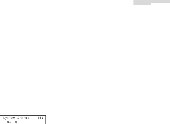
2.Press the MENU button repeatedly until "System Status" appears on the LCD.
3.Press the F1 button. SYSTEM STATUS will be displayed on Monitor 1 to 4.
Note: SYSTEM STATUS is displayed on a set of 4 monitors (Monitor 5 to 8, Monitor 9 to 12...Monitor 29 to 32).
●WV-CU360C/CJ
1.Select one of Monitor 1 to 4. (Refer to p. 21 Monitor Selection.)
2.Press the OSD and SYS S buttons at a time. SYSTEM STATUS will be displayed on Monitor 1 to 4.
Note: SYSTEM STATUS is displayed on a set of 4 monitors (Monitor 5 to 8, Monitor 9 to 12...Monitor 29 to 32).
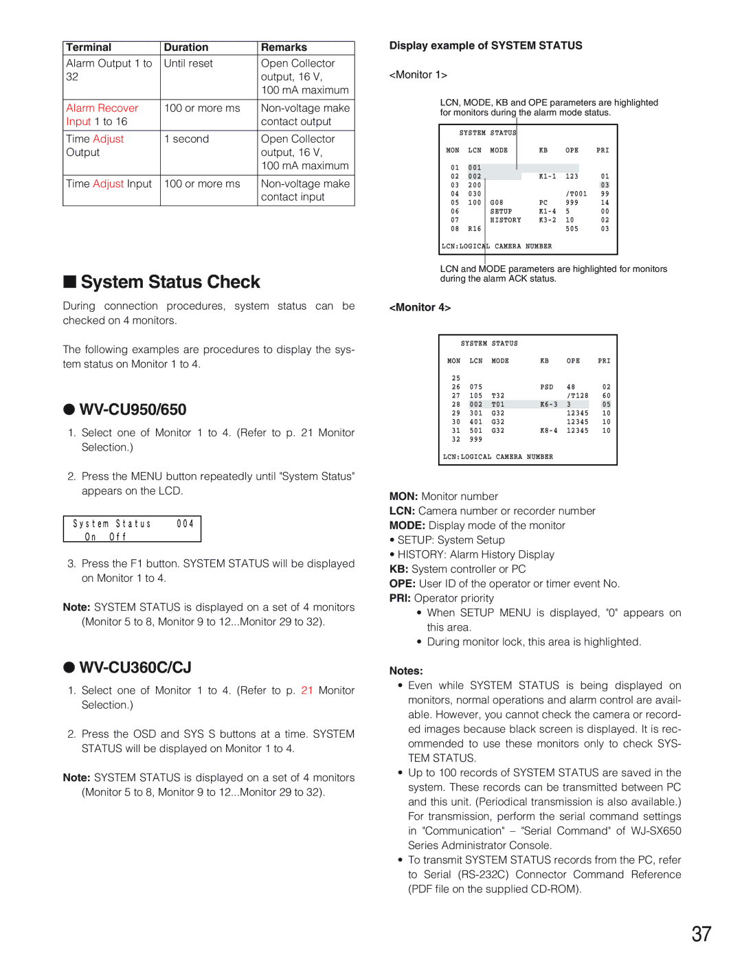
Display example of SYSTEM STATUS
<Monitor 1>
LCN, MODE, KB and OPE parameters are highlighted for monitors during the alarm mode status.
|
|
|
|
|
|
|
|
|
|
| SYSTEM | STATUS |
|
|
|
|
|
| |
MON | LCN | MODE |
| KB | OPE | PRI |
| ||
01 | 001 |
|
|
|
|
|
|
|
|
|
|
|
|
|
|
| |||
02 | 002 |
|
|
| 123 | 01 |
| ||
03 | 200 |
|
|
|
|
|
| 03 |
|
04 | 030 |
|
|
|
| /T001 | 99 |
| |
05 | 100 |
| G08 | PC | 999 | 14 |
| ||
06 |
|
| SETUP | 5 | 00 |
| |||
07 |
|
| HISTORY | 10 | 02 |
| |||
08 | R16 |
|
|
|
| 505 | 03 |
| |
LCN:LOGICAL |
| CAMERA | NUMBER |
|
|
|
| ||
|
|
|
|
|
|
|
|
|
|
|
|
|
|
|
|
|
|
|
|
LCN and MODE parameters are highlighted for monitors during the alarm ACK status.
<Monitor 4>
| SYSTEM | STATUS |
|
|
|
|
| |
MON |
| LCN | MODE | KB | OPE | PRI |
| |
25 |
|
|
|
|
|
|
|
|
26 | 075 |
| PSD | 48 | 02 |
| ||
27 | 105 | T32 |
| /T128 | 60 |
| ||
28 |
| 002 | T01 | 3 |
| 05 |
| |
29 | 301 | G32 |
| 12345 | 10 |
| ||
30 | 401 | G32 |
| 12345 | 10 |
| ||
31 | 501 | G32 | 12345 | 10 |
| |||
32 | 999 |
|
|
|
|
|
| |
LCN:LOGICAL | CAMERA | NUMBER |
|
|
|
| ||
|
|
|
|
|
|
|
|
|
MON: Monitor number
LCN: Camera number or recorder number
MODE: Display mode of the monitor
•SETUP: System Setup
•HISTORY: Alarm History Display KB: System controller or PC
OPE: User ID of the operator or timer event No.
PRI: Operator priority
•When SETUP MENU is displayed, "0" appears on this area.
•During monitor lock, this area is highlighted.
Notes:
•Even while SYSTEM STATUS is being displayed on monitors, normal operations and alarm control are avail- able. However, you cannot check the camera or record- ed images because black screen is displayed. It is rec- ommended to use these monitors only to check SYS-
TEM STATUS.
•Up to 100 records of SYSTEM STATUS are saved in the system. These records can be transmitted between PC and this unit. (Periodical transmission is also available.) For transmission, perform the serial command settings in "Communication" – "Serial Command" of
•To transmit SYSTEM STATUS records from the PC, refer to Serial
37