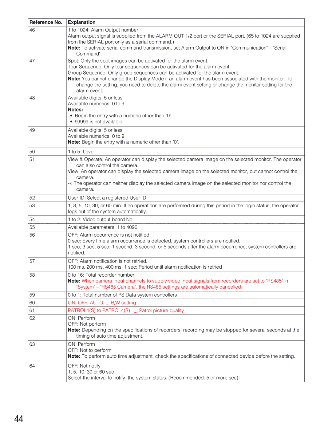
Reference No. | Explanation |
|
|
46 | 1 to 1024: Alarm Output number |
| Alarm output signal is supplied from the ALARM OUT 1/2 port or the SERIAL port. (65 to 1024 are supplied |
| from the SERIAL port only as a serial command.) |
| Note: To activate serial command transmission, set Alarm Output to ON in "Communication" – "Serial |
| Command". |
47 | Spot: Only the spot images can be activated for the alarm event. |
| Tour Sequence: Only tour sequences can be activated for the alarm event. |
| Group Sequence: Only group sequences can be activated for the alarm event. |
| Note: You cannot change the Display Mode if an alarm event has been associated with the monitor. To |
| change the setting, you need to delete the alarm event setting or change the monitor setting for the |
| alarm event. |
48 | Available digits: 5 or less |
| Available numerics: 0 to 9 |
| Notes: |
| • Begin the entry with a numeric other than "0". |
| • 99999 is not available. |
|
|
49 | Available digits: 5 or less |
| Available numerics: 0 to 9 |
| Note: Begin the entry with a numeric other than "0". |
|
|
50 | 1 to 5: Level |
|
|
51 | View & Operate: An operator can display the selected camera image on the selected monitor. The operator |
| can also control the camera. |
| View: An operator can display the selected camera image on the selected monitor, but cannot control the |
| camera. |
| |
| camera. |
|
|
52 | User ID: Select a registered User ID. |
|
|
53 | 1, 3, 5, 10, 30, or 60 min: If no operations are performed during this period in the login status, the operator |
| logs out of the system automatically. |
|
|
54 | 1 to 2: Video output board No. |
|
|
55 | Available parameters: 1 to 4096 |
|
|
56 | OFF: Alarm occurrence is not notified. |
| 0 sec: Every time alarm occurrence is detected, system controllers are notified. |
| 1 sec, 3 sec, 5 sec: 1 second, 3 second, or 5 seconds after the alarm occurrence, system controllers are |
| notified. |
|
|
57 | OFF: Alarm notification is not retried. |
| 100 ms, 200 ms, 400 ms, 1 sec: Period until alarm notification is retried |
|
|
58 | 0 to 16: Total recorder number |
| Note: When camera input channels to supply video input signals from recorders are set to "RS485" in |
| "System" – "RS485 Camera", the RS485 settings are automatically cancelled. |
|
|
59 | 0 to 1: Total number of PS·Data system controllers |
|
|
60 | ON, OFF, AUTO, _: B/W setting |
|
|
61 | PATROL1(S) to PATROL4(S) , _: Patrol picture quality |
|
|
62 | ON: Perform |
| OFF: Not perform |
| Note: Depending on the specifications of recorders, recording may be stopped for several seconds at the |
| timing of auto time adjustment. |
|
|
63 | ON: Perform |
| OFF: Not to perform |
| Note: To perform auto time adjustment, check the specifications of connected device before the setting. |
|
|
64 | OFF: Not notify |
| 1, 5, 10, 30 or 60 sec |
| Select the interval to notify the system status. (Recommended: 5 or more sec) |
|
|
44