ACCULINK 316x DSU/CSU
Overview
This chapter contains information for operating your DSU/CSU. It includes a description of the front panel and sample procedures for configuring the DSU/CSU.
NOTE
Additional information for the
Using the Front Panel
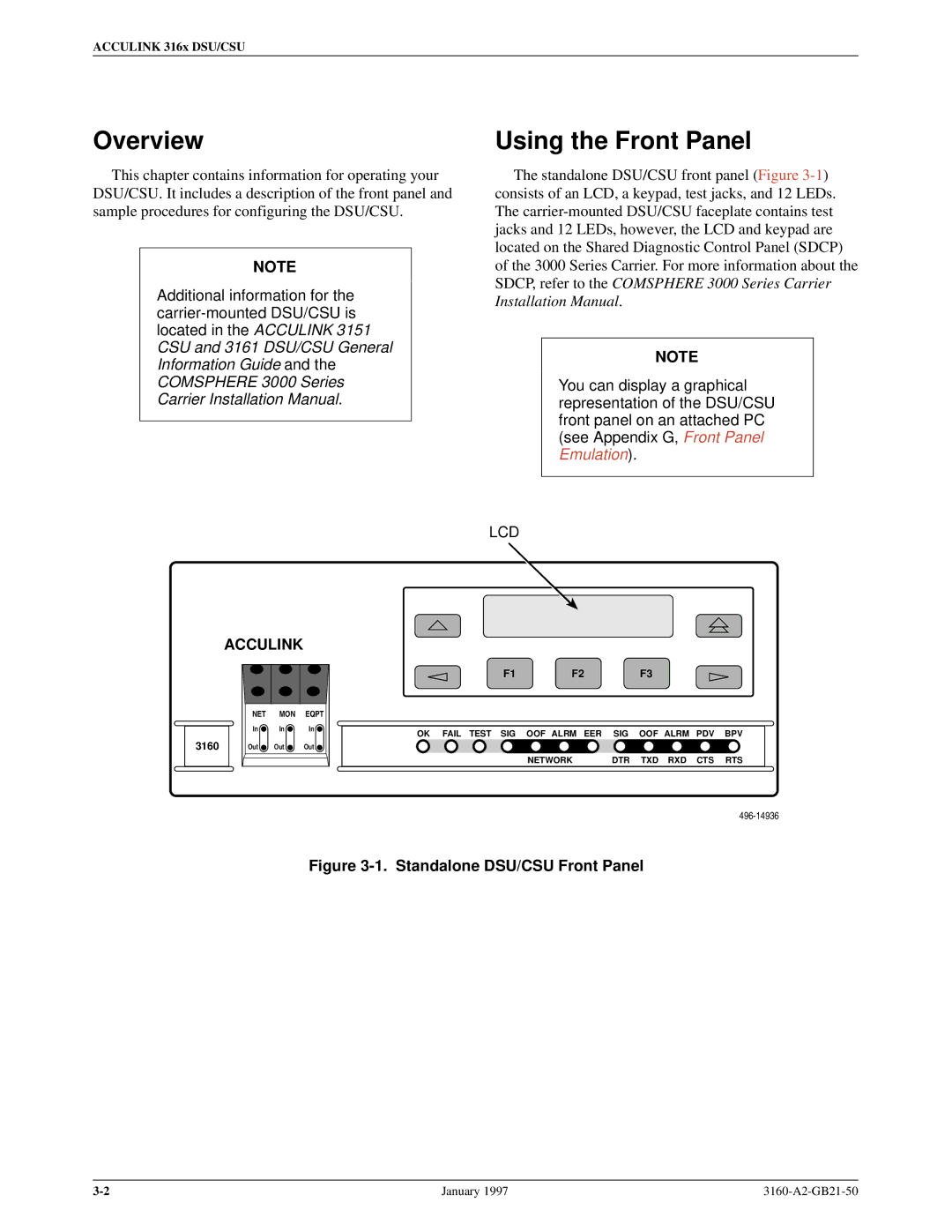
The standalone DSU/CSU front panel (Figure
NOTE
You can display a graphical representation of the DSU/CSU front panel on an attached PC (see Appendix G, Front Panel Emulation).
LCD
| ACCULINK |
| |
| NET | MON | EQPT |
| In | In | In |
3160 | Out | Out | Out |
F1F2F3
OK FAIL TEST SIG OOF ALRM EER SIG OOF ALRM PDV BPV
NETWORK | DTR TXD RXD CTS RTS |
Figure 3-1. Standalone DSU/CSU Front Panel
January 1997 |