ACCULINK 316x DSU/CSU
NOTE
The following procedures are examples only. Screen displays may vary depending on the model and configuration of the DSU/CSU.
Displaying DS0 Channel Assignments
Use the Display command (in the Channel Configuration branch) to view how the DS0 channels are currently allocated.
Line 1 of the display shows the 24 channels of the
selected interface. Pressing the ![]() or
or ![]() key scrolls the channels onto the screen in groups of three. Line 2 displays what is allocated to the DS0 channel listed in Line 1. Symbols used in the display are shown in
key scrolls the channels onto the screen in groups of three. Line 2 displays what is allocated to the DS0 channel listed in Line 1. Symbols used in the display are shown in
Table
|
| Table |
| Display Channel Symbols | |
|
|
|
Symbol |
| Meaning |
|
|
|
± |
| The DS0 channel is not allocated. |
|
|
|
Prtn |
| The DS0 channel is allocated to Port n, |
|
| where n is 1, 2, 3, or 4. |
|
|
|
Nn |
| The DS0 channel is allocated to the |
|
| network interface DS0 channel n, where |
|
| n can be any number from 1 through 24. |
|
|
|
Dn |
| The DS0 channel is allocated to the DTE |
|
| Drop/Insert |
|
| channel n, where n can be any number |
|
| from 1 through 24. |
|
|
|
To display the DS0 channel allocation,
1.From the
2.Select the configuration option set to be copied into the Edit area by using the appropriate Function key. Use the scroll keys, if necessary.
3.Select Edit.
4.From the Edit screen, press the ![]() key until the Chan selection appears on the screen.
key until the Chan selection appears on the screen.
5.Select Chan.
Edit:
Port NET Chan
F1 F2 F3
6. From the Channel Config screen, select Dsply.
Channel Config:
Dsply Clear DTE
F1 F2 F3
7.From the Display Chan screen, select NET to display the channels allocated to the network interface. Or, select DTE to display the channels allocated to the DTE Drop/Insert
Display Chan:
NET DTE Ports
F1 F2 F3
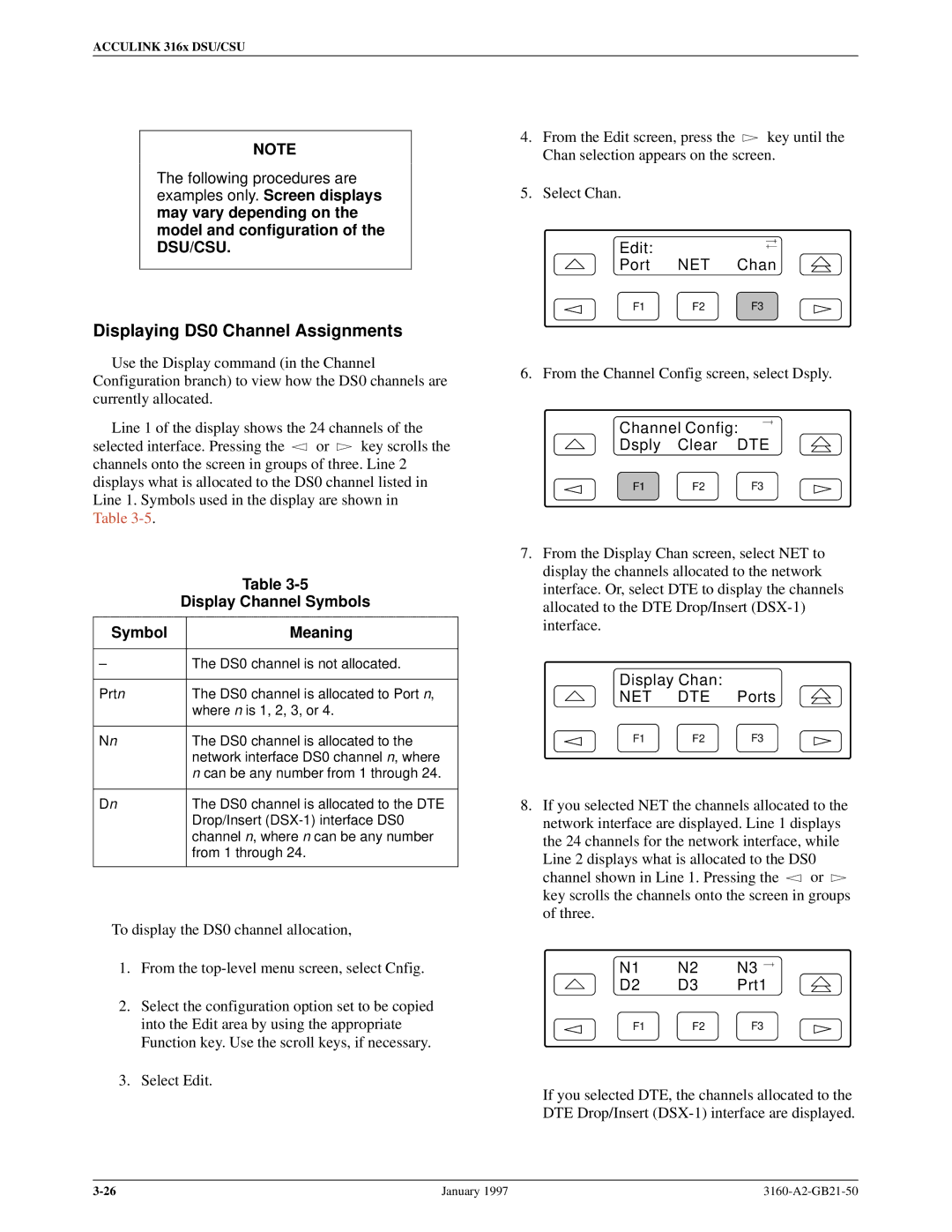
8.If you selected NET the channels allocated to the network interface are displayed. Line 1 displays the 24 channels for the network interface, while Line 2 displays what is allocated to the DS0
channel shown in Line 1. Pressing the ![]() or
or ![]() key scrolls the channels onto the screen in groups of three.
key scrolls the channels onto the screen in groups of three.
N1 | N2 | N3 |
D2 | D3 | Prt1 |
F1 | F2 | F3 |
If you selected DTE, the channels allocated to the DTE Drop/Insert
January 1997 |