ACCULINK 316x DSU/CSU
Power Input Connector
The input power connector leads are shown in Table
Table D-10
DC Power Connector
Signal | Pin Number |
|
|
±48 Vdc Return | 1, 2 |
|
|
±48 Vdc A | 6 |
|
|
±48 Vdc B | 5 |
|
|
+24 Vdc | 5 |
|
|
+24 Vdc Return | 4 |
|
|
Chassis Ground | 3 |
|
|
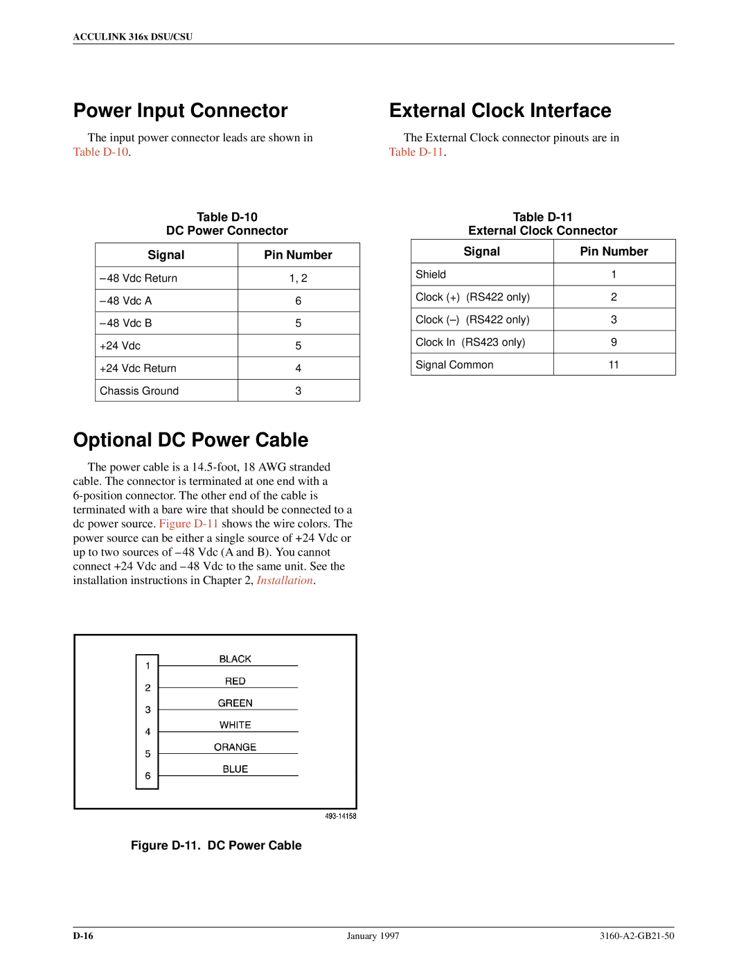
Optional DC Power Cable
The power cable is a
Figure D-11. DC Power Cable
External Clock Interface
The External Clock connector pinouts are in Table
Table D-11
External Clock Connector
| Signal | Pin Number |
|
|
|
Shield |
| 1 |
|
|
|
Clock (+) | (RS422 only) | 2 |
|
|
|
Clock (±) | (RS422 only) | 3 |
|
|
|
Clock In | (RS423 only) | 9 |
|
| |
Signal Common | 11 | |
|
|
|
January 1997 |
|