Operation
Configuring DS0 Channels
The DSU/CSU provides channel configuration options that allow you to do the following:
•Display the DS0 assignments for the network, DTE Drop/Insert
•Allocate DS0 channels on the DTE Drop/Insert
•Allocate DS0 channels on the network or DTE Drop/Insert
•Clear (deallocate) all DS0 channels from the network, DTE Drop/Insert
•Map data from one port to another.
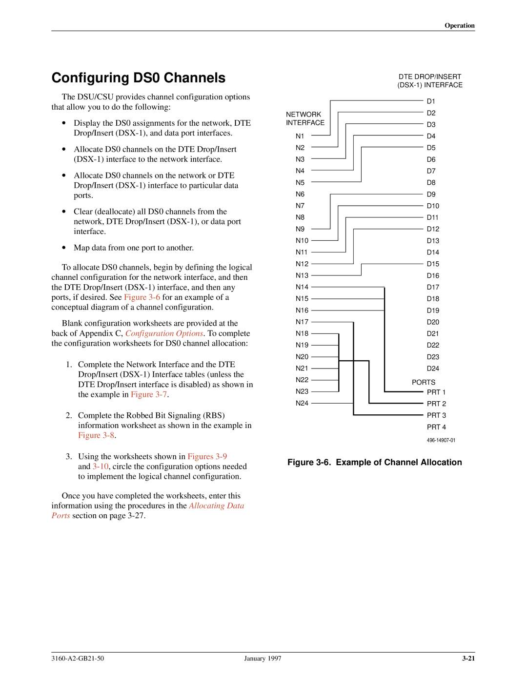
To allocate DS0 channels, begin by defining the logical channel configuration for the network interface, and then the DTE Drop/Insert
Blank configuration worksheets are provided at the back of Appendix C, Configuration Options. To complete the configuration worksheets for DS0 channel allocation:
1. | Complete the Network Interface and the DTE |
| Drop/Insert |
| DTE Drop/Insert interface is disabled) as shown in |
| the example in Figure |
2. | Complete the Robbed Bit Signaling (RBS) |
| information worksheet as shown in the example in |
| Figure |
3. | Using the worksheets shown in Figures |
NETWORK INTERFACE
N1
N2
N3
N4
N5
N6
N7
N8
N9
N10
N11
N12
N13
N14
N15
N16
N17
N18
N19
N20
N21
N22
N23
N24
DTE DROP/INSERT
D1
D2
D3
D4
D5
D6
D7
D8
D9
D10
D11
D12
D13
D14
D15
D16
D17
D18
D19
D20
D21
D22
D23
D24
PORTS
PRT 1
PRT 2
PRT 3
PRT 4
and |
to implement the logical channel configuration. |
Once you have completed the worksheets, enter this information using the procedures in the Allocating Data Ports section on page
Figure 3-6. Example of Channel Allocation
January 1997 |