Installation and Initialization
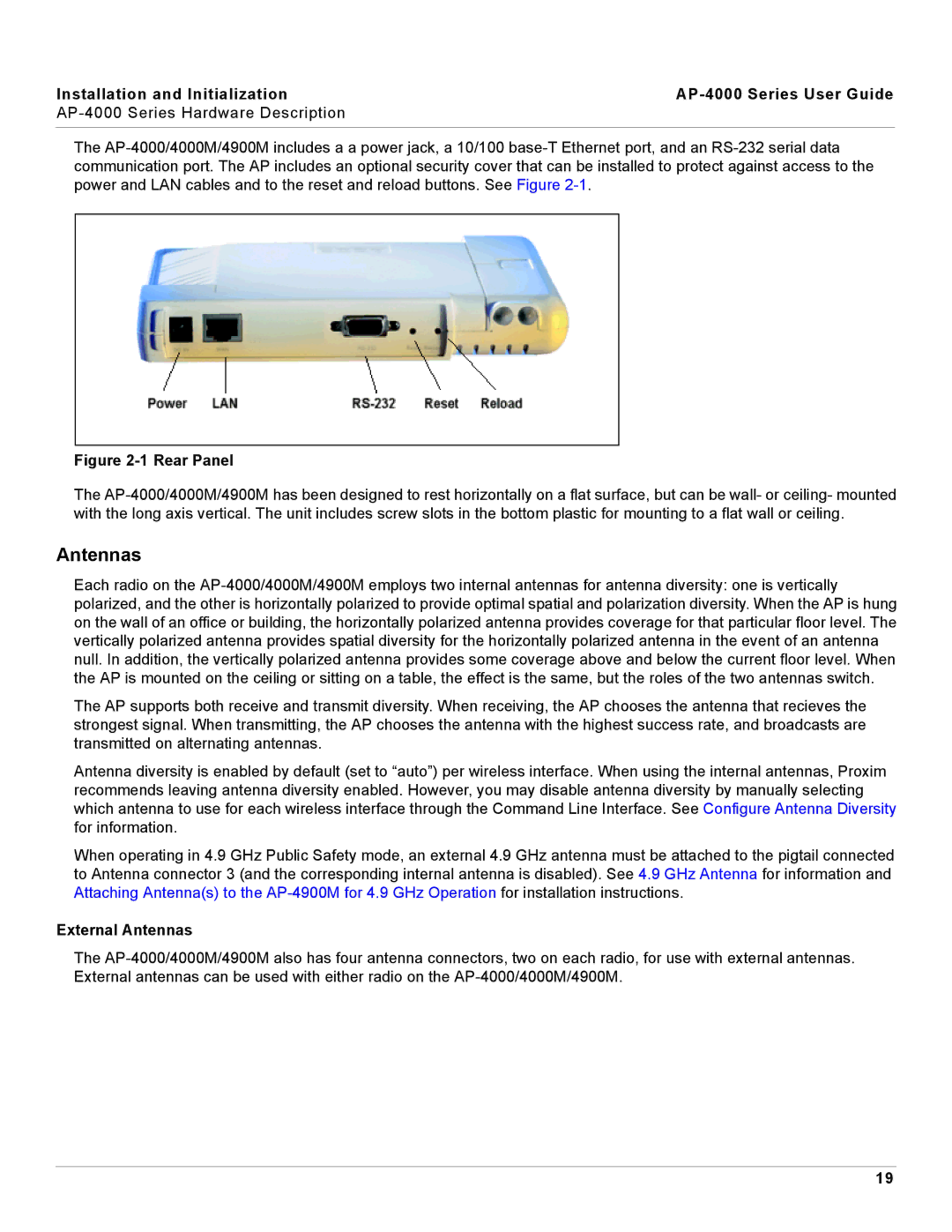
AP-4000 Series User Guide

AP-4000 Series Hardware Description


The AP-4000/4000M/4900M includes a a power jack, a 10/100 base-T Ethernet port, and an RS-232 serial data communication port. The AP includes an optional security cover that can be installed to protect against access to the power and LAN cables and to the reset and reload buttons. See Figure 2-1.

Figure 2-1 Rear Panel

The AP-4000/4000M/4900M has been designed to rest horizontally on a flat surface, but can be wall- or ceiling- mounted with the long axis vertical. The unit includes screw slots in the bottom plastic for mounting to a flat wall or ceiling.

Antennas

Each radio on the AP-4000/4000M/4900M employs two internal antennas for antenna diversity: one is vertically polarized, and the other is horizontally polarized to provide optimal spatial and polarization diversity. When the AP is hung on the wall of an office or building, the horizontally polarized antenna provides coverage for that particular floor level. The vertically polarized antenna provides spatial diversity for the horizontally polarized antenna in the event of an antenna null. In addition, the vertically polarized antenna provides some coverage above and below the current floor level. When the AP is mounted on the ceiling or sitting on a table, the effect is the same, but the roles of the two antennas switch.

The AP supports both receive and transmit diversity. When receiving, the AP chooses the antenna that recieves the strongest signal. When transmitting, the AP chooses the antenna with the highest success rate, and broadcasts are transmitted on alternating antennas.

Antenna diversity is enabled by default (set to “auto”) per wireless interface. When using the internal antennas, Proxim recommends leaving antenna diversity enabled. However, you may disable antenna diversity by manually selecting which antenna to use for each wireless interface through the Command Line Interface. See Configure Antenna Diversity for information.

When operating in 4.9 GHz Public Safety mode, an external 4.9 GHz antenna must be attached to the pigtail connected to Antenna connector 3 (and the corresponding internal antenna is disabled). See 4.9 GHz Antenna for information and Attaching Antenna(s) to the AP-4900M for 4.9 GHz Operation for installation instructions.

External Antennas

The AP-4000/4000M/4900M also has four antenna connectors, two on each radio, for use with external antennas. External antennas can be used with either radio on the AP-4000/4000M/4900M.

19

Page 19
Image 19
Proxim AP-4000 manual External Antennas