Installation and Initialization |
|
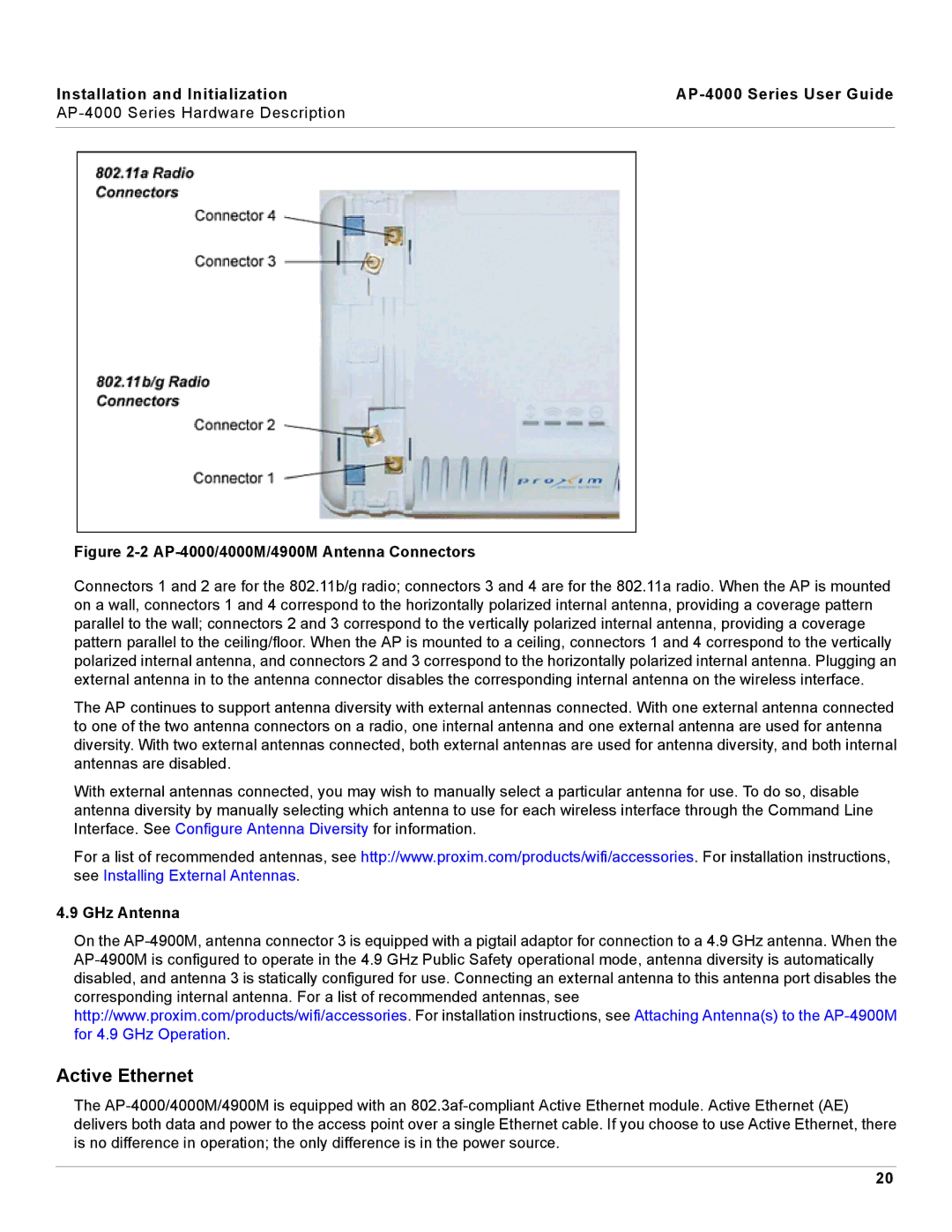
Figure 2-2 AP-4000/4000M/4900M Antenna Connectors
Connectors 1 and 2 are for the 802.11b/g radio; connectors 3 and 4 are for the 802.11a radio. When the AP is mounted on a wall, connectors 1 and 4 correspond to the horizontally polarized internal antenna, providing a coverage pattern parallel to the wall; connectors 2 and 3 correspond to the vertically polarized internal antenna, providing a coverage pattern parallel to the ceiling/floor. When the AP is mounted to a ceiling, connectors 1 and 4 correspond to the vertically polarized internal antenna, and connectors 2 and 3 correspond to the horizontally polarized internal antenna. Plugging an external antenna in to the antenna connector disables the corresponding internal antenna on the wireless interface.
The AP continues to support antenna diversity with external antennas connected. With one external antenna connected to one of the two antenna connectors on a radio, one internal antenna and one external antenna are used for antenna diversity. With two external antennas connected, both external antennas are used for antenna diversity, and both internal antennas are disabled.
With external antennas connected, you may wish to manually select a particular antenna for use. To do so, disable antenna diversity by manually selecting which antenna to use for each wireless interface through the Command Line Interface. See Configure Antenna Diversity for information.
For a list of recommended antennas, see http://www.proxim.com/products/wifi/accessories. For installation instructions, see Installing External Antennas.
4.9 GHz Antenna
On the
Active Ethernet
The
20
