Installation and Initialization |
|
| |
|
|
•The Active Ethernet (AE) integrated module receives ~48 VDC over a standard Category 5 Ethernet cable.
•To use Active Ethernet, you must have an AE hub (also known as a power injector) connected to the network.
•The cable length between the AE hub and the Access Point should not exceed 100 meters (approximately 325 feet). The AE hub is not a repeater and does not amplify the Ethernet data signal.
•If connected to an AE hub and an AC power simultaneously, the Access Point draws power from Active Ethernet.
Also see Hardware Specifications.
NOTE: The AP’s
LED Indicators
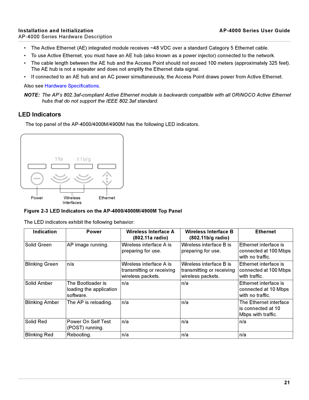
The top panel of the
Power Wireless Ethernet
Interfaces
Figure 2-3 LED Indicators on the AP-4000/4000M/4900M Top Panel
The LED indicators exhibit the following behavior:
Indication | Power | Wireless Interface A | Wireless Interface B | Ethernet |
|
| (802.11a radio) | (802.11b/g radio) |
|
Solid Green | AP image running. | Wireless interface A is | Wireless interface B is | Ethernet interface is |
|
| preparing for use. | preparing for use. | connected at 100 Mbps |
|
|
|
| with no traffic. |
Blinking Green | n/a | Wireless interface A is | Wireless interface B is | Ethernet interface is |
|
| transmitting or receiving | transmitting or receiving | connected at 100 Mbps |
|
| wireless packets. | wireless packets. | with traffic. |
Solid Amber | The Bootloader is | n/a | n/a | Ethernet interface is |
| loading the application |
|
| connected at 10 Mbps |
| software. |
|
| with no traffic. |
Blinking Amber | The AP is reloading. | n/a | n/a | The Ethernet interface |
|
|
|
| is connected at 10 |
|
|
|
| Mbps with traffic. |
Solid Red | Power On Self Test | n/a | n/a | n/a |
| (POST) running. |
|
|
|
Blinking Red | Rebooting. | n/a | n/a | n/a |
21