Cycle and reaction times 5.5 Interrupt response time
Calculation
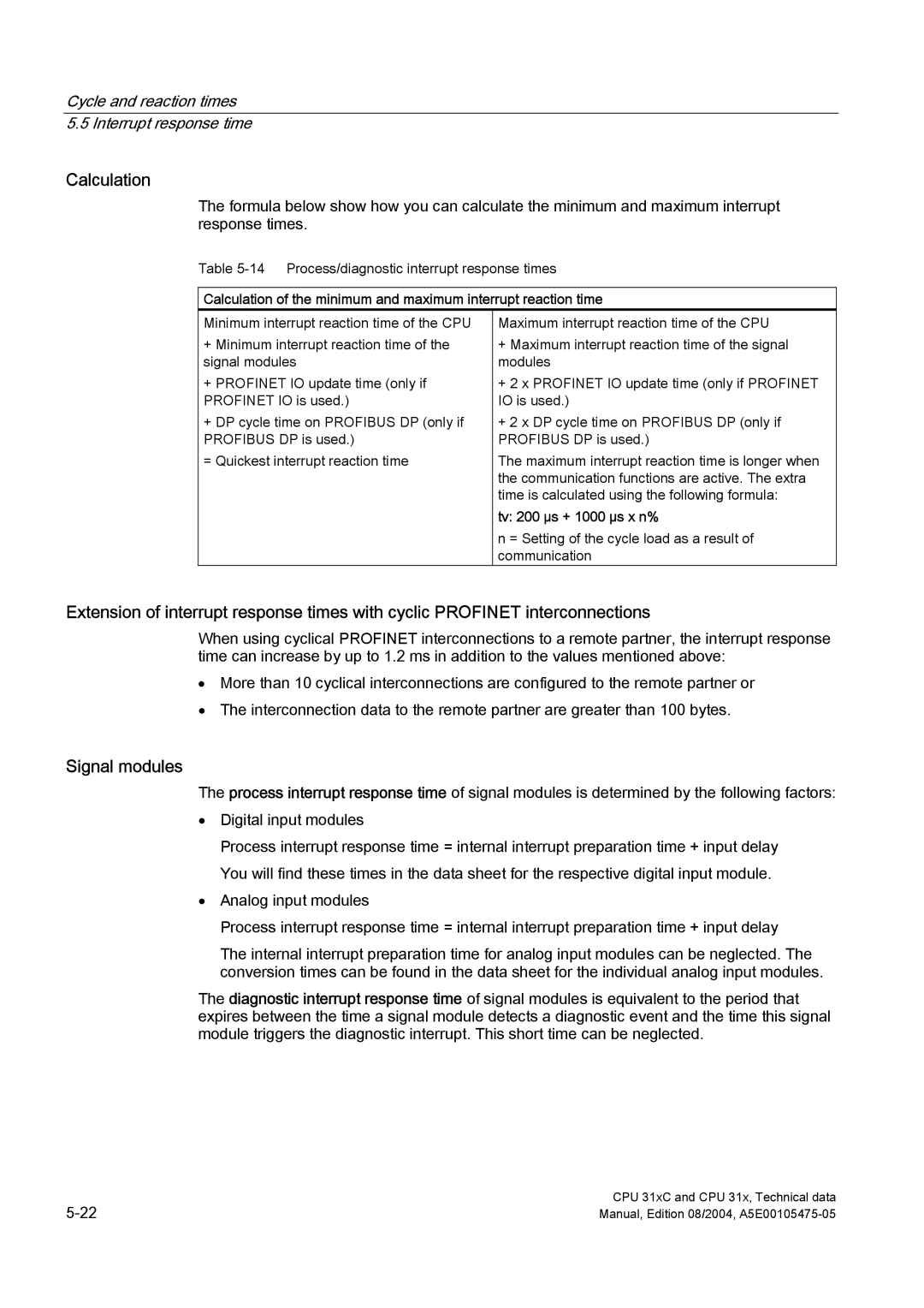
The formula below show how you can calculate the minimum and maximum interrupt response times.
Table
Calculation of the minimum and maximum interrupt reaction time
Minimum interrupt reaction time of the CPU | Maximum interrupt reaction time of the CPU |
+ Minimum interrupt reaction time of the | + Maximum interrupt reaction time of the signal |
signal modules | modules |
+ PROFINET IO update time (only if | + 2 x PROFINET IO update time (only if PROFINET |
PROFINET IO is used.) | IO is used.) |
+ DP cycle time on PROFIBUS DP (only if | + 2 x DP cycle time on PROFIBUS DP (only if |
PROFIBUS DP is used.) | PROFIBUS DP is used.) |
= Quickest interrupt reaction time | The maximum interrupt reaction time is longer when |
| the communication functions are active. The extra |
| time is calculated using the following formula: |
| tv: 200 μs + 1000 μs x n% |
| n = Setting of the cycle load as a result of |
| communication |
Extension of interrupt response times with cyclic PROFINET interconnections
When using cyclical PROFINET interconnections to a remote partner, the interrupt response time can increase by up to 1.2 ms in addition to the values mentioned above:
•More than 10 cyclical interconnections are configured to the remote partner or
•The interconnection data to the remote partner are greater than 100 bytes.
Signal modules
The process interrupt response time of signal modules is determined by the following factors:
•Digital input modules
Process interrupt response time = internal interrupt preparation time + input delay You will find these times in the data sheet for the respective digital input module.
•Analog input modules
Process interrupt response time = internal interrupt preparation time + input delay
The internal interrupt preparation time for analog input modules can be neglected. The conversion times can be found in the data sheet for the individual analog input modules.
The diagnostic interrupt response time of signal modules is equivalent to the period that expires between the time a signal module detects a diagnostic event and the time this signal module triggers the diagnostic interrupt. This short time can be neglected.
CPU 31xC and CPU 31x, Technical data | |
Manual, Edition 08/2004, |
