Technical data of CPU 31xC
6.6 Technical data of the integrated I/O
6.6.2Analog I/O
Wiring of the current/voltage inputs
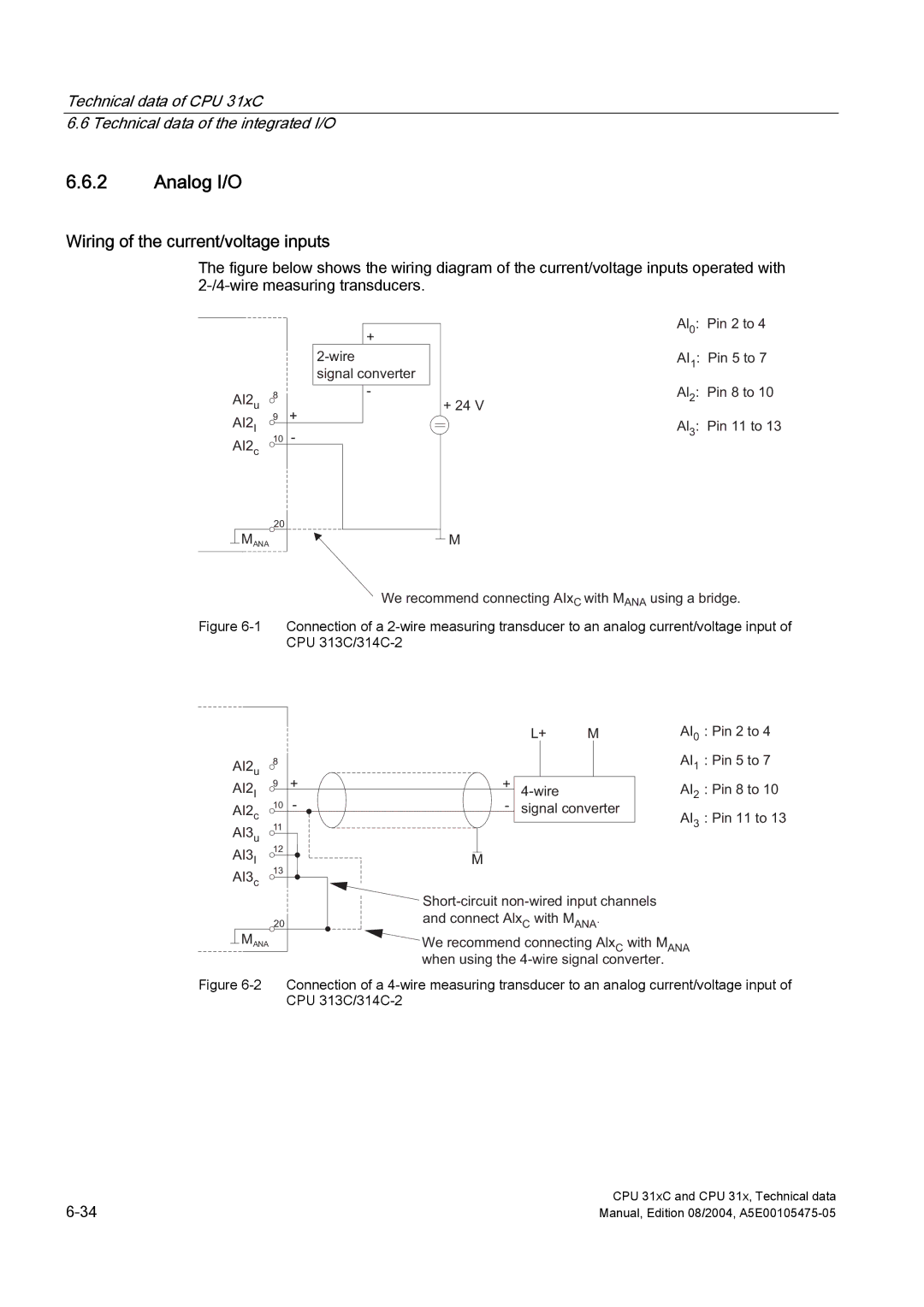
The figure below shows the wiring diagram of the current/voltage inputs operated with 2-/4-wire measuring transducers.
|
|
|
|
|
|
|
|
|
|
|
|
|
|
|
| + |
|
|
|
|
|
|
| |||
|
|
|
|
| signal converter |
| ||
|
|
|
|
|
|
|
| |
8 |
|
|
| - |
| |||
|
|
|
| |||||
AI2u | + |
|
|
|
| |||
9 |
|
|
|
| ||||
AI2I |
|
|
|
|
|
|
| |
|
| - |
|
|
|
| ||
10 |
|
|
|
| ||||
AI2c |
|
|
|
|
|
| ||
|
|
|
|
|
| |||
|
|
|
|
|
|
|
|
|
20
MANA
+ 24 V
M
Al0: Pin 2 to 4
AI1: Pin 5 to 7
Al2: Pin 8 to 10
Al3: Pin 11 to 13
We recommend connecting AIxC with MANA using a bridge.
Figure 6-1 Connection of a 2-wire measuring transducer to an analog current/voltage input of CPU 313C/314C-2
|
|
|
| L+ | M | AI0 : Pin 2 to 4 |
AI2u | 8 |
|
|
|
| AI1 : Pin 5 to 7 |
|
|
|
|
|
| |
AI2I | 9 | + | + |
| AI2 : Pin 8 to 10 | |
AI2c | 10 | - | - | signal converter | AI3 : Pin 11 to 13 | |
AI3u | 11 |
|
|
|
| |
|
|
|
|
| ||
|
|
|
|
|
| |
AI3I | 12 |
|
|
|
|
|
|
| M |
|
|
| |
AI3c | 13 |
|
|
|
|
|
|
|
|
|
|
| |
|
|
|
|
|
| |||
| 20 |
| and connect AlxC with MANA. |
|
|
| ||
|
|
|
|
| ||||
|
| MANA |
| We recommend connecting Alx | C | with M | ANA | |
|
|
| ||||||
|
|
|
|
|
|
| ||
when using the
Figure 6-2 Connection of a 4-wire measuring transducer to an analog current/voltage input of CPU 313C/314C-2
CPU 31xC and CPU 31x, Technical data | |
Manual, Edition 08/2004, |