Cycle and reaction times 5.2 Cycle time
5.2.2Calculating the cycle time
Introduction
The cycle time is derived from the sum of the following influencing factors.
Process image update
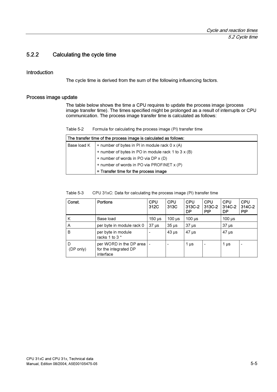
The table below shows the time a CPU requires to update the process image (process image transfer time). The times specified might be prolonged as a result of interrupts or CPU communication. The process image transfer time is calculated as follows:
Table
The transfer time of the process image is calculated as follows:
Base load K
+number of bytes in PI in module rack 0 x (A)
+number of bytes in PO in module rack 1 to 3 x (B)
+number of words in PO via DP x (D)
+number of words in PO via PROFINET x (P)
=Transfer time for the process image
Table
Const. | Portions | CPU | CPU | CPU | CPU | CPU | CPU |
|
| 312C | 313C |
|
| ||
|
|
|
| DP | PtP | DP | PtP |
K | Base load | 150 μs | 100 μs | 100 μs |
| 100 μs |
|
A | per byte in module rack 0 | 37 μs | 35 μs | 37 μs |
| 37 μs |
|
B | per byte in module | - | 43 μs | 47 μs |
| 47 μs |
|
| racks 1 to 3 * |
|
|
|
|
|
|
D | per WORD in the DP area | - | - | 1 μs | - | 1 μs | - |
(DP only) | for the integrated DP |
|
|
|
|
|
|
| interface |
|
|
|
|
|
|
CPU 31xC and CPU 31x, Technical data | |
Manual, Edition 08/2004, |