Operating and display elements 2.2 Operating and display elements: CPU 31x
2.2Operating and display elements: CPU 31x
2.2.1Operating and display elements: CPU 312, 314, 315-2 DP:
Operating and display elements
6
5
4
| 1 |
SF |
|
BF |
|
DC5V |
|
FRCE |
|
RUN |
|
STOP |
|
| RUN |
| STOP |
| MRES |
X1 | X2 |
MMC
2
3
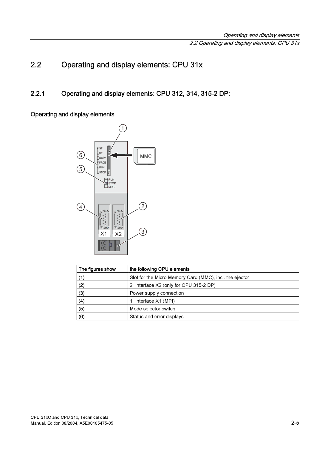
The figures show | the following CPU elements |
(1) | Slot for the Micro Memory Card (MMC), incl. the ejector |
(2) | 2. Interface X2 (only for CPU |
(3) | Power supply connection |
(4) | 1. Interface X1 (MPI) |
(5) | Mode selector switch |
(6) | Status and error displays |
CPU 31xC and CPU 31x, Technical data | |
Manual, Edition 08/2004, |