Technical data of CPU 31xC
6.6 Technical data of the integrated I/O
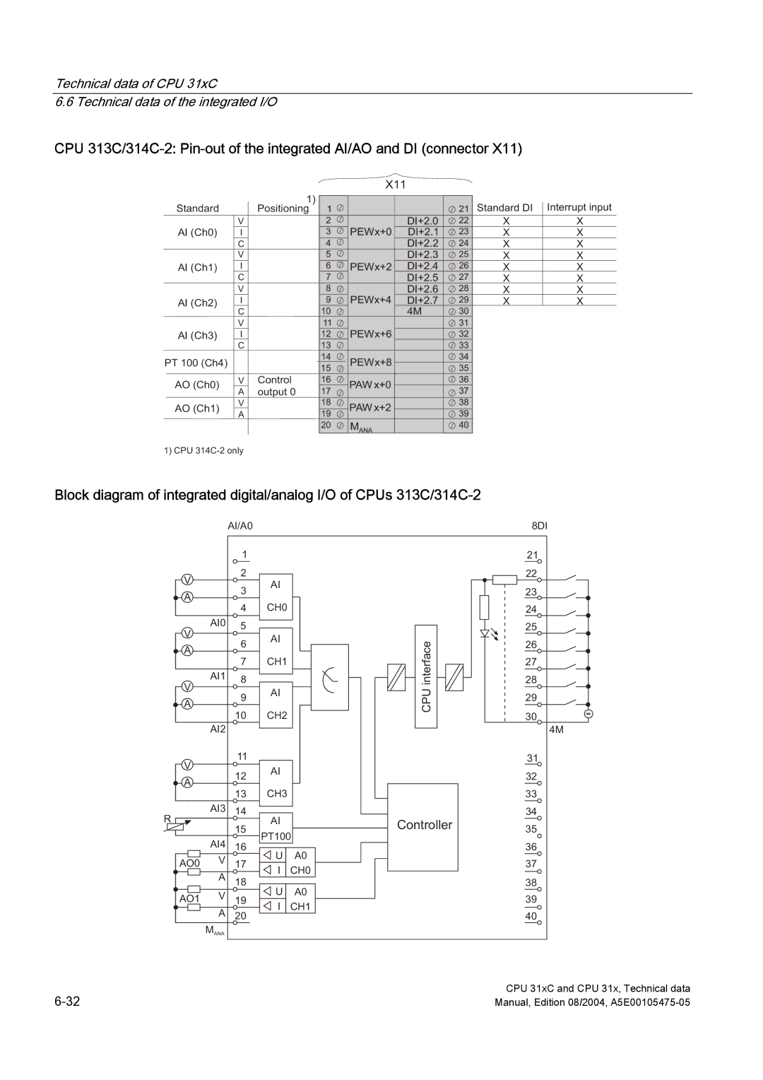
CPU
Standard
AI (Ch0)
AI (Ch1)
AI (Ch2)
AI (Ch3)
PT 100 (Ch4)
AO (Ch0)
AO (Ch1)
V
I
C V
I
C V
I
C V
I
C
V
A V
A
X11
1) |
|
|
|
| Standard DI | Interrupt input |
Positioning | 1 |
|
| 21 | ||
| 2 |
| DI+2.0 | 22 | X | X |
| 3 | PEWx+0 | DI+2.1 | 23 | X | X |
| 4 |
| DI+2.2 | 24 | X | X |
| 5 |
| DI+2.3 | 25 | X | X |
| 6 | PEWx+2 | DI+2.4 | 26 | X | X |
| 7 |
| DI+2.5 | 27 | X | X |
| 8 |
| DI+2.6 | 28 | X | X |
| 9 | PEWx+4 | DI+2.7 | 29 | X | X |
| 10 |
| 4M | 30 |
|
|
| 11 |
|
| 31 |
|
|
| 12 | PEWx+6 |
| 32 |
|
|
| 13 |
|
| 33 |
|
|
| 14 | PEWx+8 |
| 34 |
|
|
| 15 |
| 35 |
|
| |
|
|
|
|
| ||
Control | 16 | PAW x+0 |
| 36 |
|
|
output 0 | 17 |
| 37 |
|
| |
|
|
|
| |||
| 18 | PAW x+2 |
| 38 |
|
|
| 19 |
| 39 |
|
| |
|
|
|
|
| ||
| 20 | MANA |
| 40 |
|
|
1) CPU
Block diagram of integrated digital/analog I/O of CPUs
|
| AI/A0 |
|
| 8DI | |
|
| 1 |
|
| 21 | |
V |
| 2 |
|
| 22 | |
|
| AI |
|
| ||
|
| 3 |
| 23 | ||
A |
|
|
| |||
|
|
|
|
| ||
|
| 4 | CH0 |
| 24 | |
| AI0 | 5 |
|
| 25 | |
V |
|
|
| |||
|
| AI | interface |
| ||
|
| 6 | 26 | |||
A |
|
| ||||
|
|
|
| |||
|
| 7 | CH1 | 27 | ||
V | AI1 | 8 |
| 28 | ||
|
| AI | CPU |
| ||
|
| 9 | 29 | |||
A |
|
| ||||
|
|
|
| |||
|
| 10 | CH2 | 30 | ||
|
|
| ||||
| AI2 |
|
|
| 4M | |
V |
| 11 |
|
| 31 | |
|
| AI |
|
| ||
|
| 12 |
| 32 | ||
A |
|
|
| |||
|
|
|
|
| ||
|
| 13 | CH3 |
| 33 | |
R | AI3 | 14 | AI |
| 34 | |
| 15 | Controller | 35 | |||
|
|
| ||||
|
| PT100 | ||||
| AI4 |
|
| |||
| 16 | U | A0 | 36 | ||
AO0 | V | 17 | 37 | |||
I | CH0 | |||||
| A |
|
| |||
| 18 | U | A0 | 38 | ||
AO1 | V | 19 | 39 | |||
I | CH1 | |||||
| A | 20 |
| |||
|
|
| 40 | |||
| MANA |
|
|
|
| |
CPU 31xC and CPU 31x, Technical data | |
Manual, Edition 08/2004, |