Technical data of CPU 31xC
6.6 Technical data of the integrated I/O
Byte 0
Byte 1
Byte 2
| 7 |
|
|
|
|
|
|
| 0 | |
|
|
|
|
|
|
|
|
| Interrupt input DI +0.0 | |
|
|
|
|
|
|
| Interrupt input DI +0.1 | |||
| Interrupt input DI +0.7 |
|
| |||||||
|
|
|
|
|
|
|
|
|
|
|
| 7 |
|
|
|
|
|
|
| 0 | |
|
|
|
|
|
|
|
|
| Interrupt input DI +1.0 | |
|
|
|
|
|
|
| Interrupt input DI +1.1 | |||
| Interrupt input DI +1.7 |
|
| |||||||
|
|
|
|
|
|
|
|
|
|
|
| 7 |
|
|
|
|
|
|
| 0 | |
|
|
|
|
|
|
|
|
| Interrupt input DI +2.0 | |
|
|
|
|
|
|
| Interrupt input DI +2.1 | |||
| Interrupt input DI +2.7 |
| 0: deactivated | |||||||
|
|
|
|
|
|
|
|
|
| 1: rising edge |
|
|
|
|
|
|
|
|
|
| Default setting: |
Byte 3 reserved
Byte 4
Byte 5
| 7 |
|
|
|
|
|
| 0 | |
|
|
|
|
|
|
|
| Interrupt input DI +0.0 | |
|
|
|
|
|
|
| Interrupt input DI +0.1 | ||
| Interrupt input |
|
|
|
| ||||
|
|
|
|
|
|
|
|
|
|
| 7 |
|
|
|
|
|
| 0 | |
Interrupt input DI +1.0
Interrupt input DI +1.1 Interrupt input DI +1.7
Byte 6 7 | 0 |
Interrupt input DI +2.0 Interrupt input DI +2.1
Interrupt input DI +2.7 0: deactivated
1: rising edge Default setting:
Byte 7 reserved
Byte 8
Byte 9
7 | 0 |
Input delay DI +0.0 to DI +0.3 Input delay DI +0.4 to DI +0.7
Input delay DI +1.0 to DI +1.3
Input delay DI +1.4 to DI +1.7
7 | 0 |
Input delay DI +2.0 to DI +2.3
Input delay DI +2.4 to DI +2.7
reserved | 00B: | 3 | ms |
|
|
| |||
| 01B: | 0,1 ms |
| |
| 10B: | 0,5 ms |
| |
| 11B: 15 | ms |
| |
| Default setting: | 00B | ||
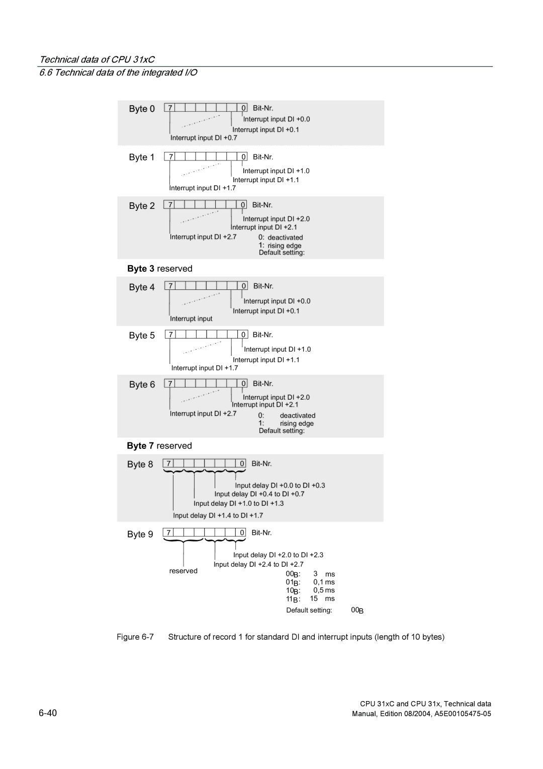
Figure 6-7 Structure of record 1 for standard DI and interrupt inputs (length of 10 bytes)
CPU 31xC and CPU 31x, Technical data | |
Manual, Edition 08/2004, |